
-
-
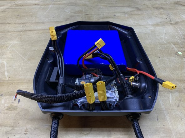
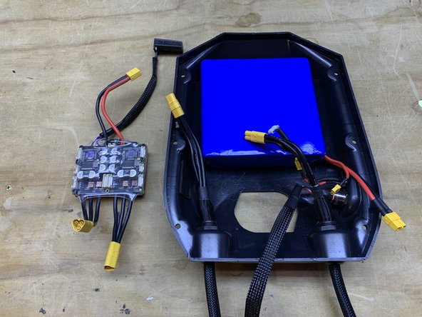
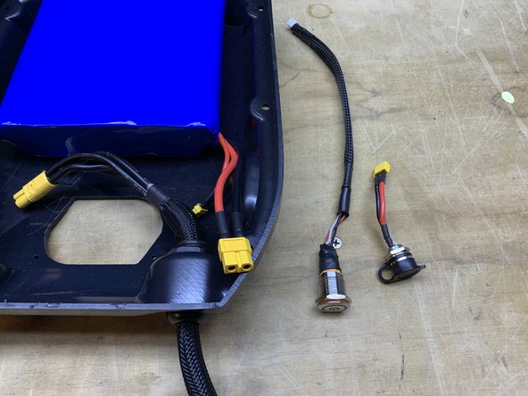
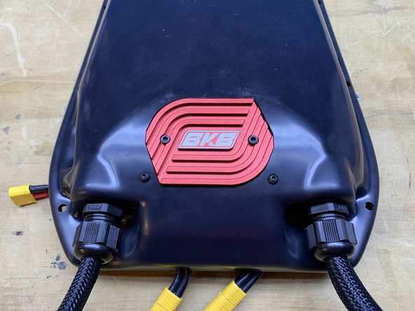
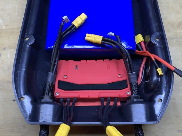
Remove the enclosure from the deck and set aside the mounting hardware
-
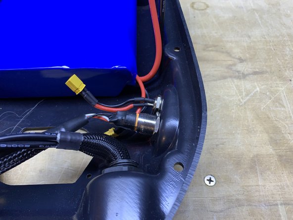
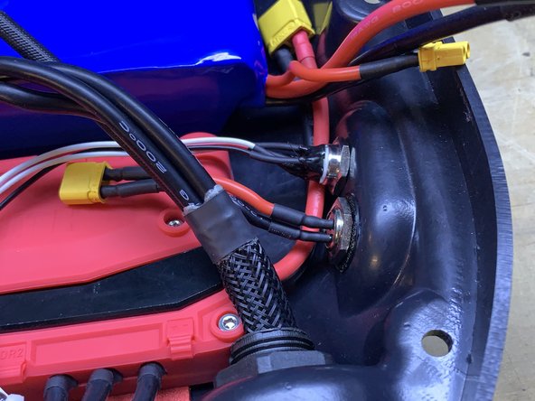
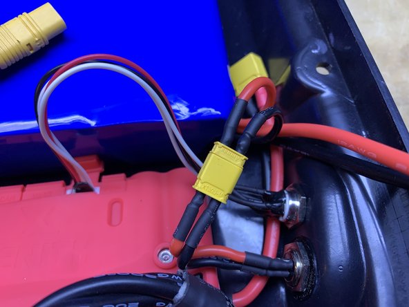
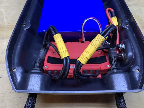
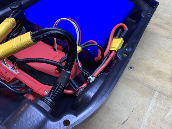
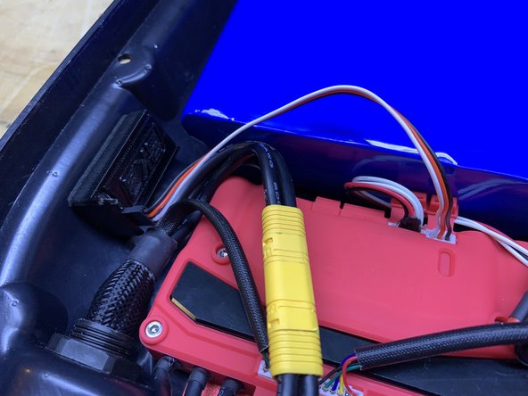
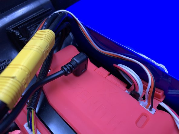
Unplug the motors, battery, and charge port
-
-
-
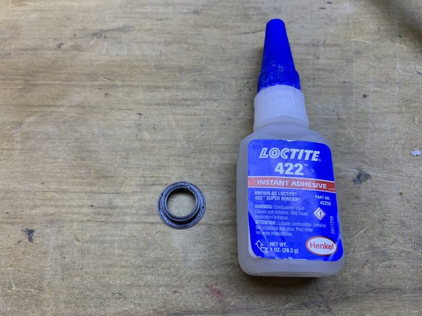
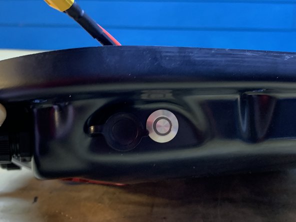
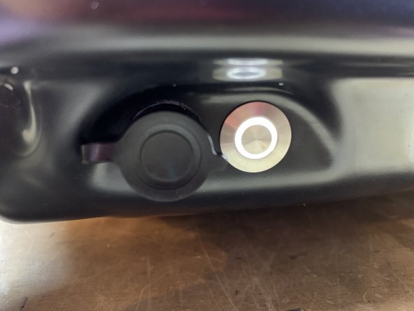
Since the switch on the Xenith is smaller, you will need an enclosure spacer to fill in the gaps. Please email use after placing your order so we can include one free of charge.
-
If you already have your Xenith and didn't receive one, you can download the STL and 3d print it yourself (file is at the bottom of this guide). If you do not have a printer we will send one if you cover the shipping.
-
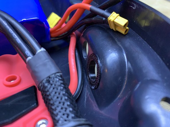
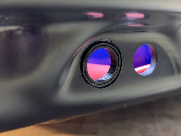
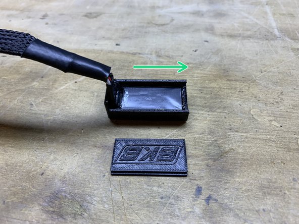
Place adhesive (superglue) on the outer rim of the spacer. Then press it into the enclosure with the rim inwards.
-
-
-
Download the VESC Tool from this link
-
Click the download button in the upper right hand corner.
-
Once the file is downloaded, navigate to your downloads folder and unzip the compressed file VESC Tool 2.06.zip
-
Open the folder and double click vesc_tool_2.06
-
If you get a blue security popup click more info, Run Anyway
-
-
-
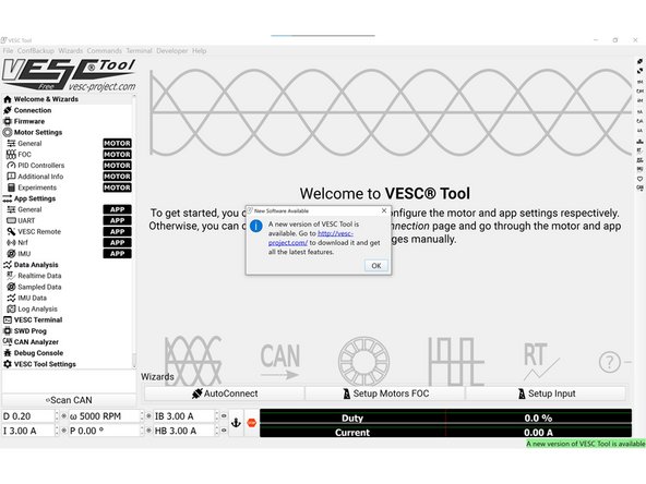
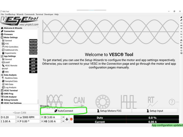
Once the VESC Tool is open you should get a popup saying that there is a new version available. Ignore this and click OK
-
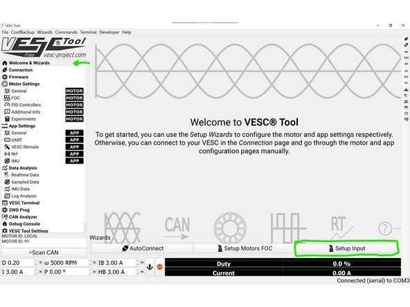
Click the AutoConnect button at the bottom of the screen. The VESC Tool should say Connected COM# in the bottom right
-
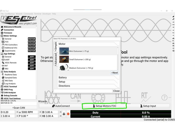
Click Setup Motors FOC at the bottom of the screen
-
-
-
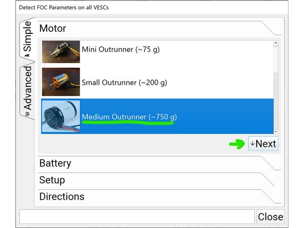
Select Medium Outrunner and then click next
-
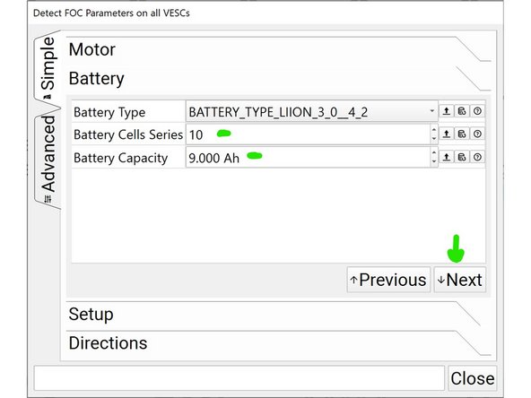
Change the battery cells series value to 10 and the capacity to 9.00Ah. Click next
-
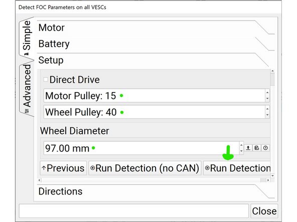
Change the motor pulley value to 15, wheel pulley to 40, and wheel diameter to 97 (if you have the speed upgrade, 48t pulley, or other wheels these values should be different). Then click run detection.
-
-
-
You will then get a popup saying that the motors will spin and to make sure everything is clear. Verify that nothing will get caught by the wheels spinning, and then click ok.
-
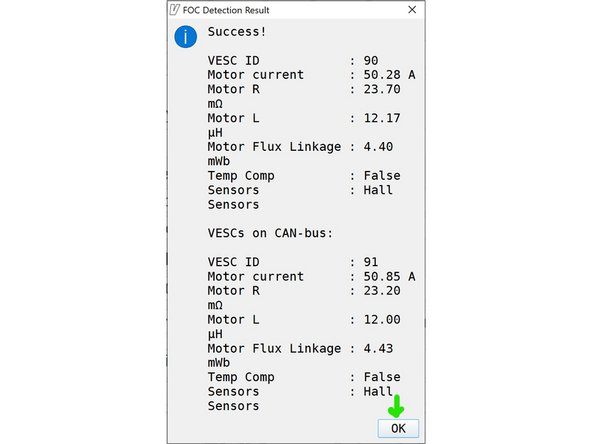
When the motor detection is completed you will get a popup similar to this (your values will be slightly different). Click ok
-
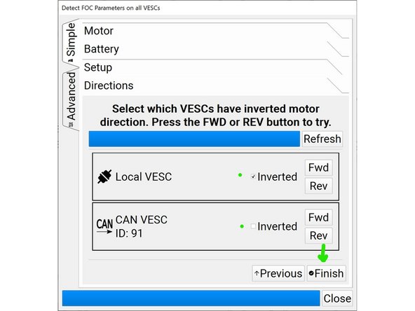
Now its time to select the motor direction. You can click FWD on each motor to spin it in the forward direction. To determine which direction is correct place your finger on top of the motor with light force. Then click the FWD button and see what way the motor takes your finger.
-
If it drags your finger in towards the truck, it is spinning in the proper direction.
-
If it drags your finger out towards the enclosure it is spinning in the wrong direction. Select the inverted box next to the FWD button and repeat the process. It should now drag your finger in towards the trucks.
-
Repeat this process for LOCAL VESC motor and CAN VESC motor. Both motors should spin in towards the truck
-
Then click finish
-
-
-
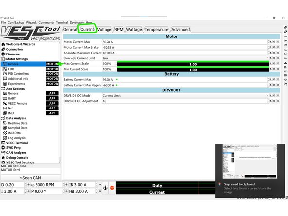
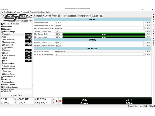
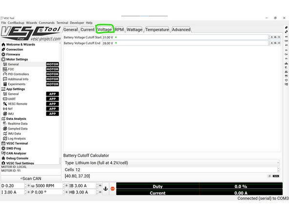
Then navigate to the Voltage tab at the top of the screen
-
Change the Battery Voltage Cutoff Start value to 31.00 V
-
Change the Battery Voltage Cutoff End value to 28.00V
-
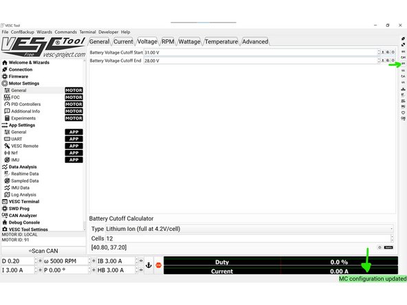
Click the downward M arrow on the right side of the screen
-
At the bottom right of the VESC tool it will say MC Configuration Updated
-
-
-
As it stands now, the remote indication will not work on the remote. This is because there is no voltage wire. So the light will continually blink.
-
We are working on an adaptor cable to ensure the battery indication works (timeline TBD for availability).
-
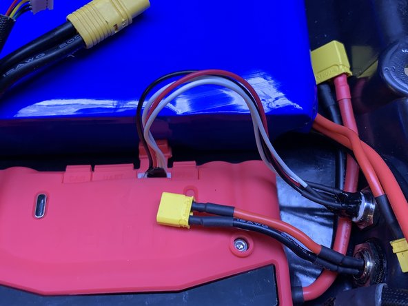
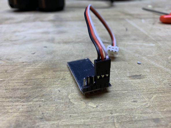
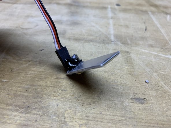
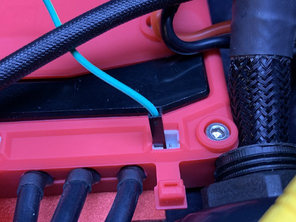
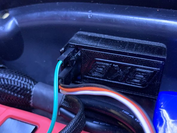
In the mean time, you can use an Arduino jumper wire to connect the + voltage from the Xenith to the outer most pin on the receiver. This will allow the battery indication to work.
-
If you do this MAKE SURE to secure the wire!! Use some kind of hot glue or adhesive to make sure the wire does not come out of the Xenith OR the receiver
-


Cancel: I did not complete this guide.
One other person completed this guide.
Attached Documents

One Comment
It would be nice if you guys included instructions for UART in this guide. I bought a Xenith with a VX2 Pro remote from you guys and the remote only supports UART. Using UART, it’s not possible to complete step 24 of this guide. It seems to work without that step, but it’d be helpful if the guide explained that or said what to do instead of ppm setup.
Alek Gent-Vincent - Resolved on Release Reply