
-
-
Thanks for joining the Lectec Beta program! We are so excited to have you and your little engineer assemble the kit! If you have any questions throughout the process, please text Jared at: 570-442-7066
-
Please remember to film as much as possible! A major part of this program is the content generated by the beta testers. Here are some things to keep in mind:
-
Please film horizontal with your smart device (HD or 4K is fine) at 24p or 30p.
-
Film wide shots of work area during assembly of the board, and of all the components.
-
Film close ups of your hands, tools, screws during process.
-
Videos of each other’s faces (children AND parents)! We want to see smiles and focus/dedication to the task at hand.
-
Film your child while they ride, ensure they have a helmet on (board, smiles, riding shots).
-
Please upload all content to our OneDrive folder. Even photos/videos that you think are bad, we want it all!
-
-
-
This project is desinged to be completed by a child accompanied by an adult. It is not simple enough for a child to do on their own
-
It is expected to take 2-3 hours to complete. It may be best to break the process up into multiple 30-45 minute chunks.
-
Be sure to read each step carefully and click on the 2nd and 3rd photo from each step. Every step has a photo associated to it (you just need to click on it)
-
-
-
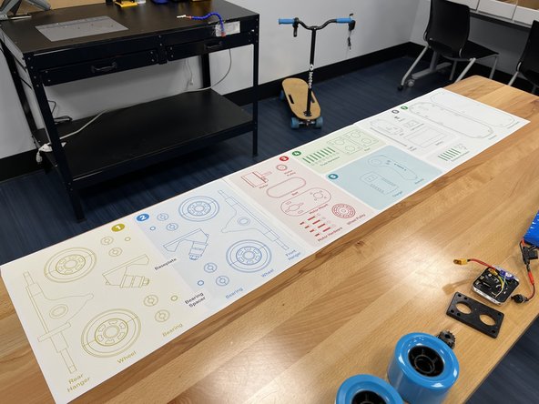
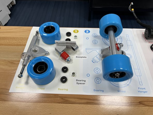
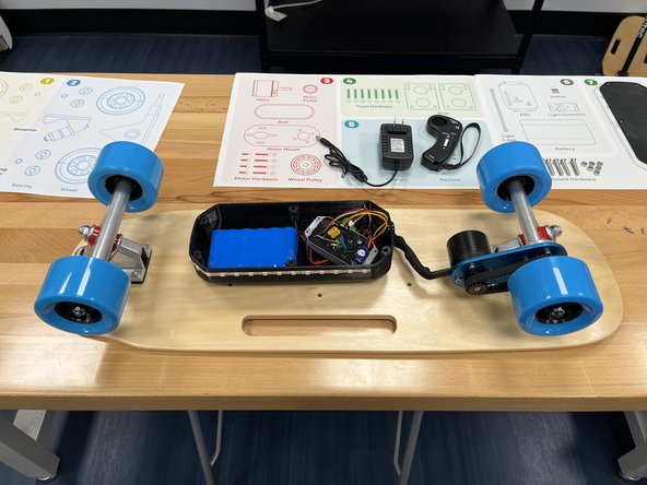
To get started, lay out the 3 work mats on a table
-
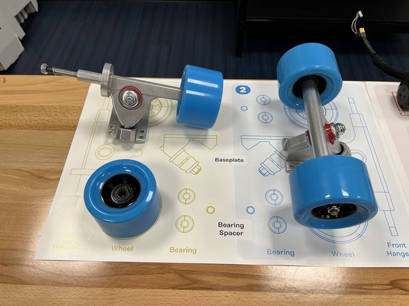
Place all of the components from the box on to the proper space on the work mat.
-
The deck, tool kit, and 4x Phillips screws will not be on the mat. Be sure not to misplace them
-
We installed the bearings and bearing spacers into the wheels and the enclosure nuts in to the enclosure to simplify things for you. They will not need to be placed on the mat
-
Bag A = Motor Hardware
-
Bag B = Truck Hardware
-
Bag C = Enclosure Hardware (+4 Phillips screws not pictured on mat, leave in the bag until used)
-
-
-
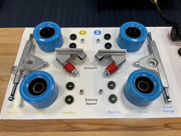
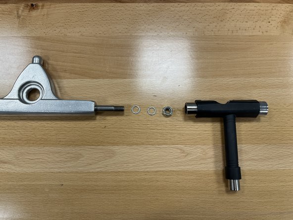
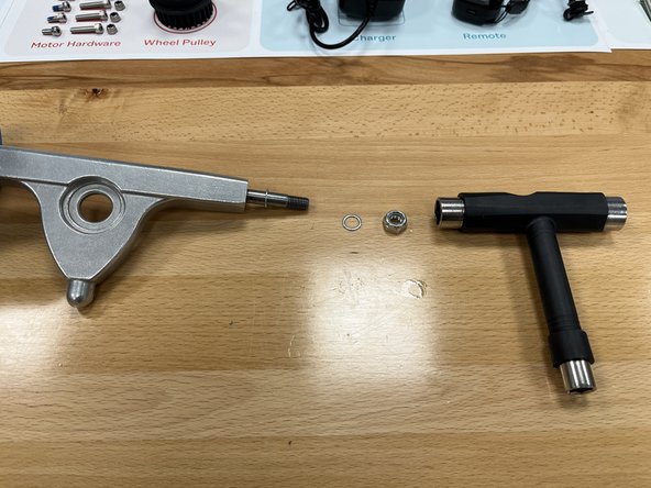
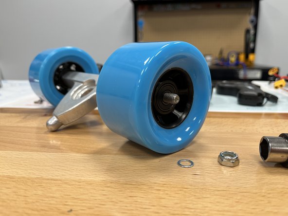
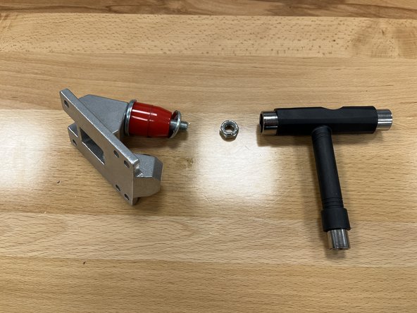
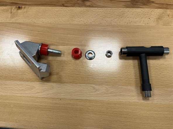
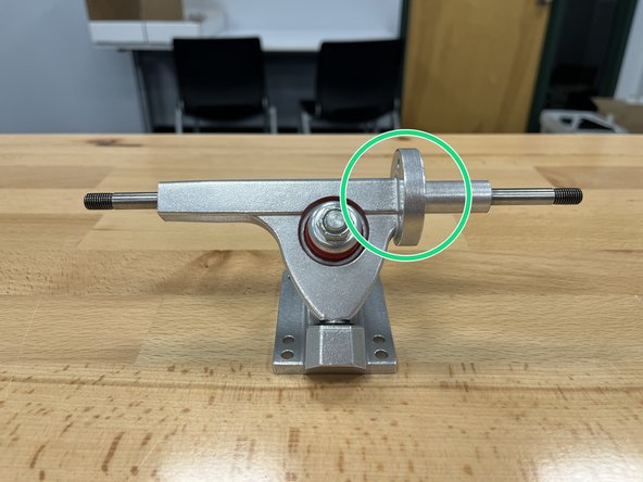
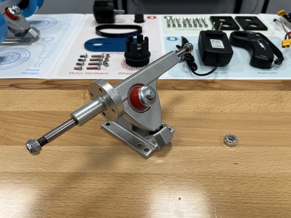
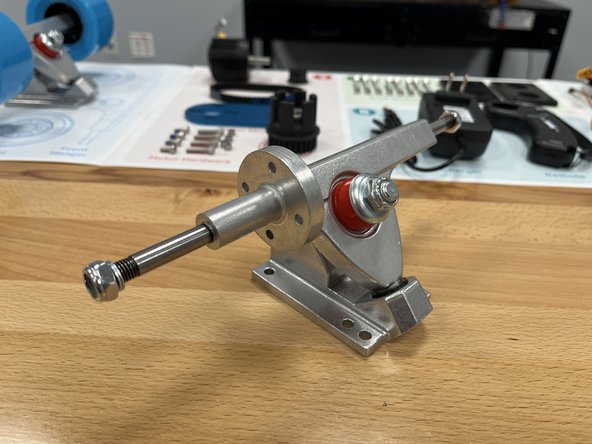
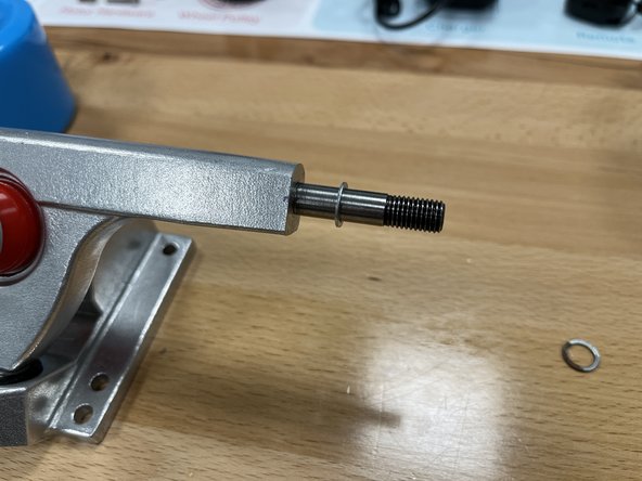
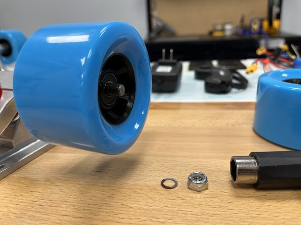
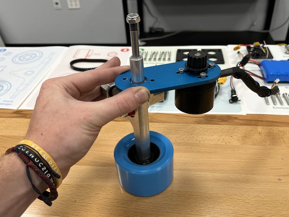
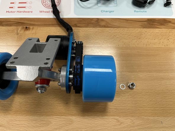
Remove the locknut and 1 silver washer from the Front Hanger in section 2 using the T-Tool. One silver washer should remain on the front truck (this photo shows both of them removed)
-
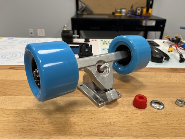
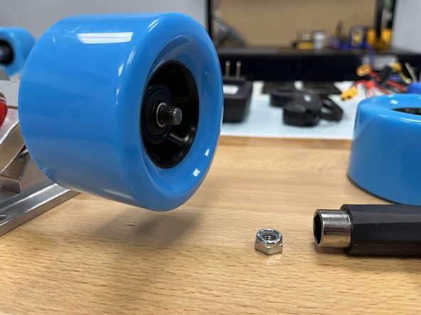
Place one silver spacer back onto the hanger (you removed them earlier)
-
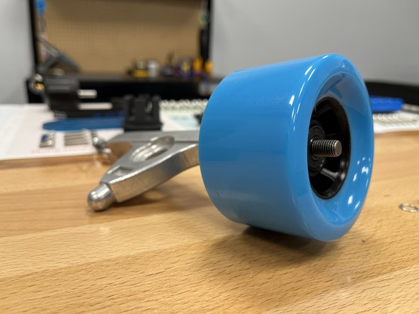
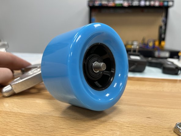
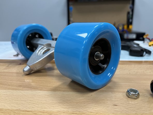
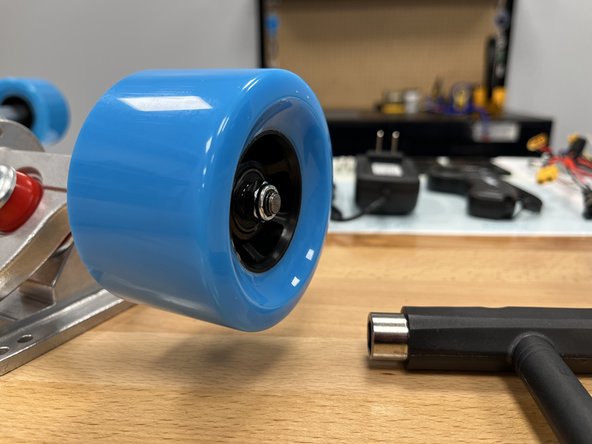
Slide the wheel onto the truck with the rounded and smooth side facing towards you. Knock the wheel back and forth if the bearing spacer is in the way and then wheel will not slide on
-
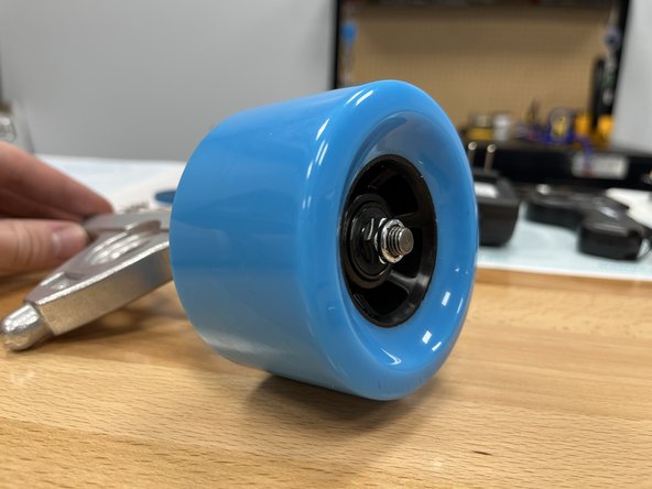
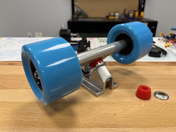
Place the other silver spacer onto the hanger
-
-
-
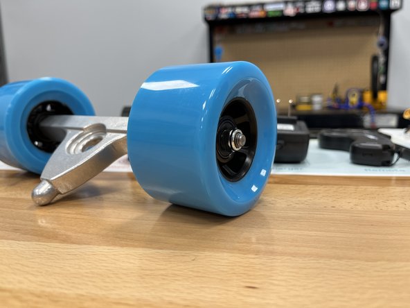
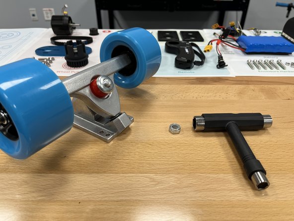
Place the locknut onto the hanger and tighten using the T-Tool
-
Tighten the locknut until it does not turn anymore. Then back it off 1/4 turn to get the proper tightness.
-
You should be able to spin the wheel freely with little friction. If it is hard to spin the wheel, loosen the locknut
-
-
-
Remove the locknut and One (1) silver spacer from the other side of the hanger. One silver spacer should remain on the hanger.
-
Slide the other wheel onto the hanger. Knock the wheel if necessary to align the bearing spacer.
-
Slide the silver spacer back onto the hanger
-
-
-
Place the locknut onto the hanger and tighten using the T-Tool
-
Tighten the locknut until it does not turn anymore. Then back it off 1/4 turn to get the proper tightness.
-
You should be able to spin the wheel freely with little friction. If it is hard to spin the wheel, loosen the locknut
-
-
-
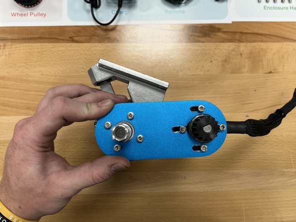
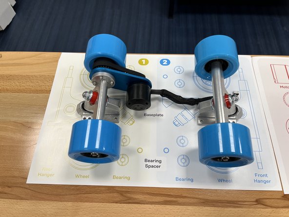
Gather the baseplate from Section 2
-
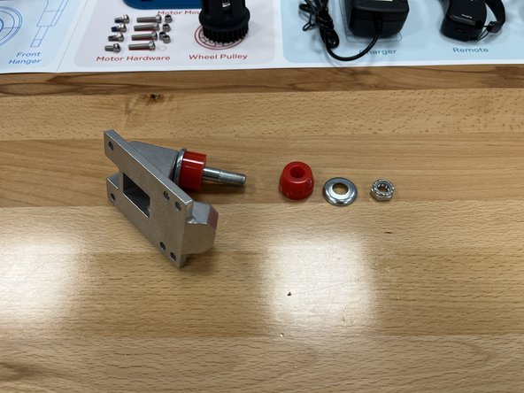
Using the T-Tool, remove the locknut from the baseplate
-
Remove the silver washer and one red bushing
-
-
-
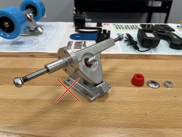
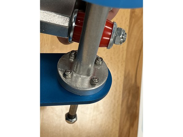
Place the hanger into the baseplate as shown. The top round part should fit inside the black pivot cup inside the baseplate.
-
The words on one side of the truck should be facing away from you
-
-
-
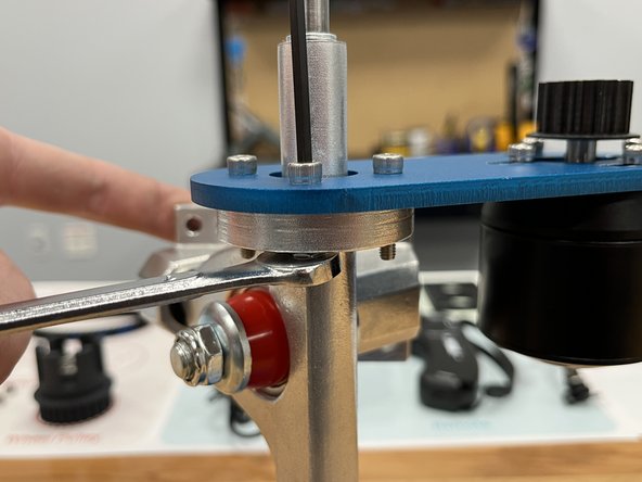
Place the red bushing back onto the truck with the smaller end toward the end of the bolt
-
Place the silver washer back on top of the red bushing with the cupped side towards the bushing
-
Add the locknut back onto the bolt and tighten until the bolt is flush with the locknut
-
Place the completed front truck onto section 2! Great job so far!
-
-
-
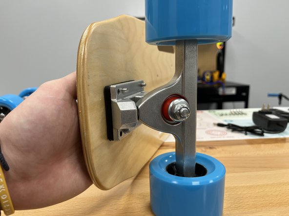
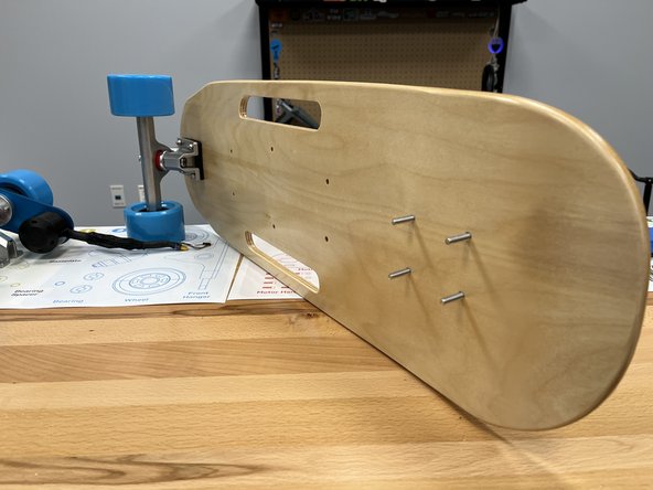
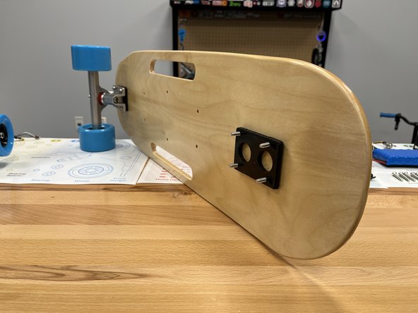
Gather the baseplate from Section 1
-
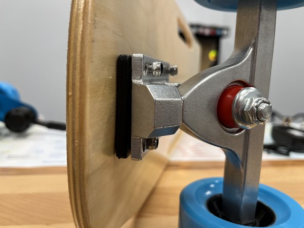
The second image, and rest of the tutorial, show the motor mount positioned on the left side. This is not correct, and should be placed on the right side as shown in the third photo
-
Remove the locknut, silver washer, and one red bushing
-
Place the Rear Hanger from Section 1 into the baseplate
-
-
-
Place the red bushing back onto the truck with the smaller end toward the end of the bolt
-
Place the silver washer back on top of the red bushing with the cupped side towards the bushing
-
Add the locknut back onto the bolt and tighten slightly
-
-
-
Remove the locknut and one silver spacer from the rear hanger on the side without the extra circular block.
-
Slide the wheel onto the truck with the rounded and smooth side facing towards you. Knock the wheel back and forth if the bearing spacer is in the way and then wheel will not slide on
-
Place the other silver spacer onto the hanger
-
-
-
Place the locknut onto the hanger and tighten using the T-Tool
-
Tighten the locknut until it does not turn anymore. Then back it off 1/4 turn to get the proper tightness.
-
You should be able to spin the wheel freely with little friction. If it is hard to spin the wheel, loosen the locknut
-
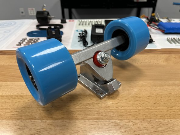
Place the rear truck and 1 loose wheel back onto Section 1 of the work mat
-
-
-
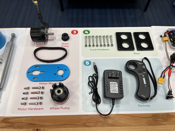
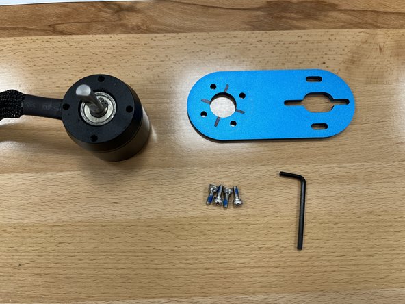
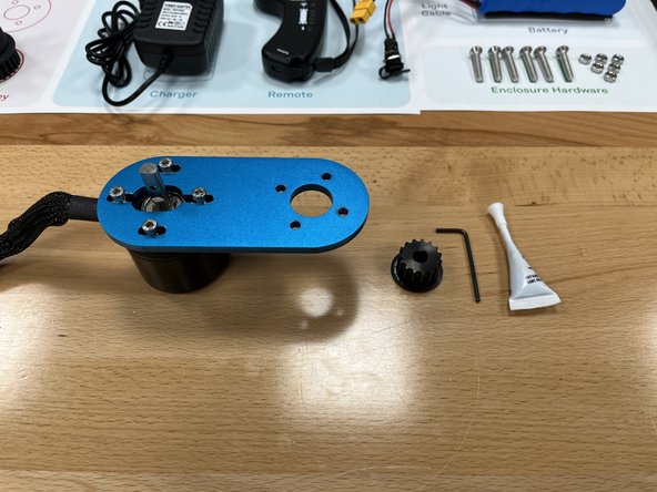
Gather the motor mount, motor, short M4x10 bolts, and larger 3mm Allen Wrench from Section 3
-
One side of the motor mount will have black lines on it. This side is the back, and is the correct side to install the motor on. The bolts will go on the OPPOSITE side.
-
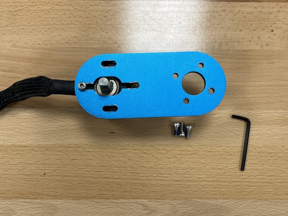
Place the motor mount onto the motor as shown. The wire should exit directly left of the motor mount, and you should NOT see the black marks.
-
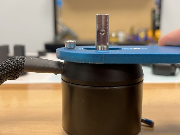
Attach the motor mount with one short M4 bolt. Do NOT tighten it all the way. There should be a small gap between the bolt and the motor mount still
-
-
-
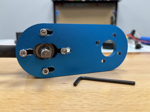
Install the other three bolts, do NOT tighten them fully
-
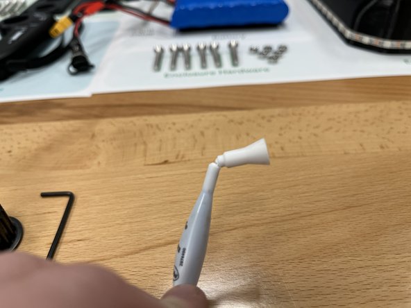
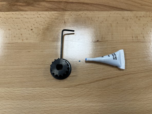
Gather the motor pulley from section 3 and the Loctite from the Tool Kit.
-
Open the loctite by breaking the top off as shown in the photo
-
-
-
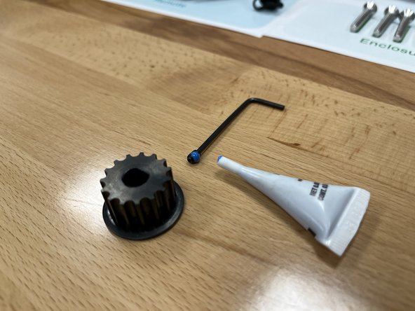
Remove the set screw from the motor pulley using the smaller 2mm Allen Wrench
-
Place a drop of blue Loctite onto the set screw
-
Use the 2mm Allen Wrench to reinstall the set screw (you should not see it on the inside)
-
-
-
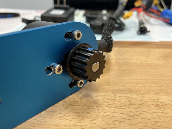
Slide the motor pulley onto the motor shaft, make sure it is flush with the end of the shaft (and not pushed all the way in).
-
Use the 2mm Allen Wrench to tighten the set screw completely. The set screw should no longer move on the shaft.
-
-
-
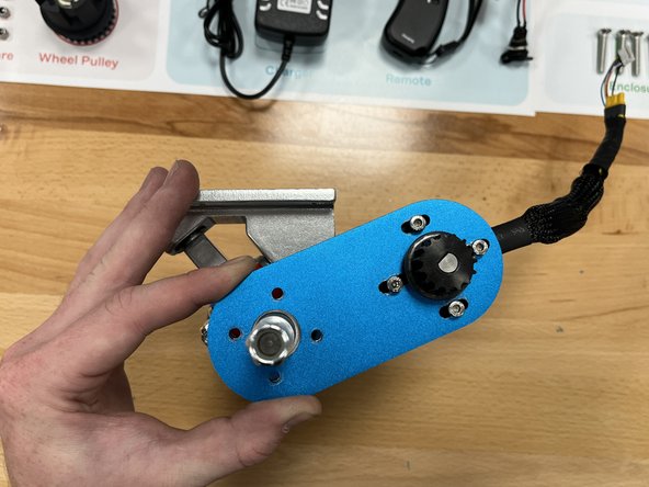
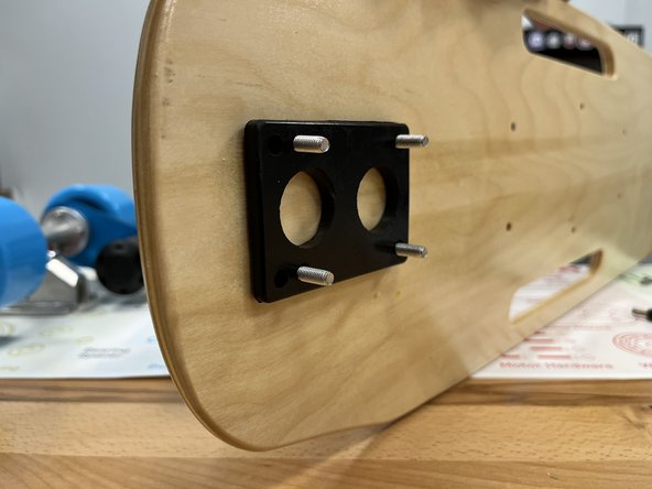
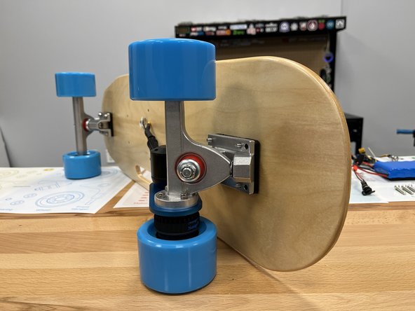
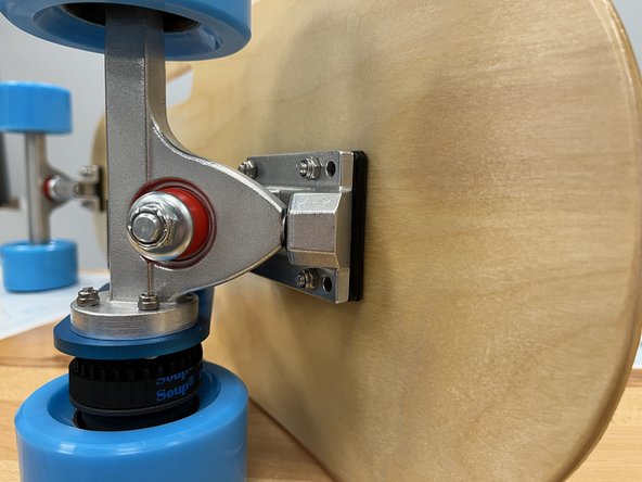
Place the motor mount onto the rear hanger and align the mounting holes as shown
-
Note the orientation of the truck and motor mount. You can install the motor mount on the wrong side as the holes will line up in multiple spots. Ensure the baseplate and motor mount are orientated as shown.
-
Add the 4x long motor hardware bolts from section 3 to the motor mount
-
-
-
Add the 4 locknuts from the motor hardware in section 3 to the back of the motor mount.
-
Tighten all four bolts with the 7mm spanner wrench and allen wrench
-
-
-
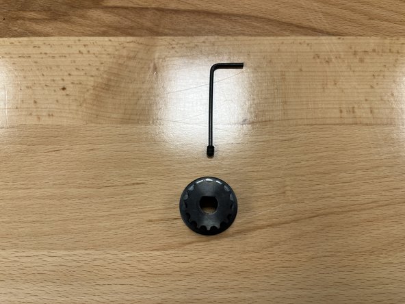
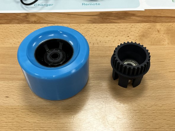
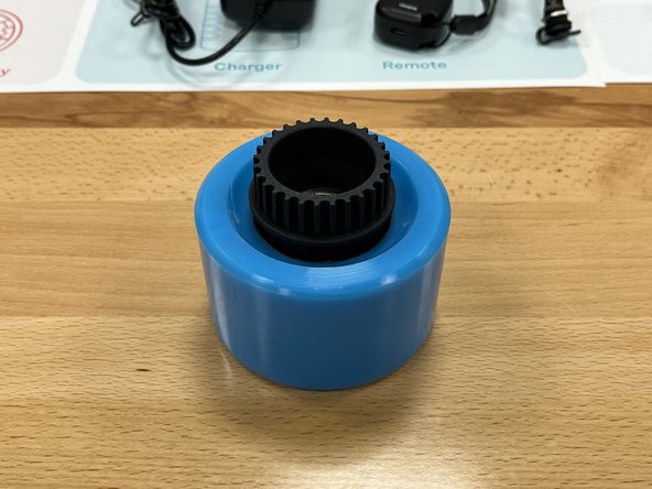
Gather the wheel pulley from section 3 and the wheel from section 1
-
Place the wheel pulley into the wheel on the flat side with the lines (not the rounded front).
-
-
-
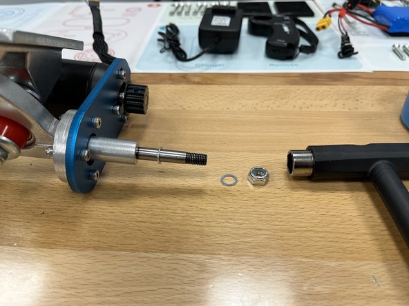
Use the T-Tool to remove the locknut and 1 silver spacer from the rear hanger
-
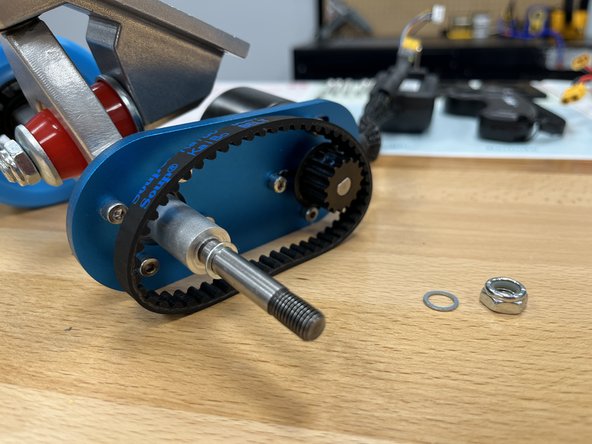
Place the belt over the motor pulley as shown
-
Slide the wheel + pulley onto the rear hanger and position the belt over both pulleys
-
If you cannot fit the belt on, loosen the 4 bolts that hold the motor on and slide it toward the hanger
-
-
-
Place the silver spacer back onto the hanger
-
Place the locknut onto the hanger and tighten using the T-Tool
-
Tighten the locknut until it does not turn anymore. Then back it off 1/4 turn to get the proper tightness.
-
You should be able to spin the wheel freely with little friction. If it is hard to spin the wheel, loosen the locknut
-
-
-
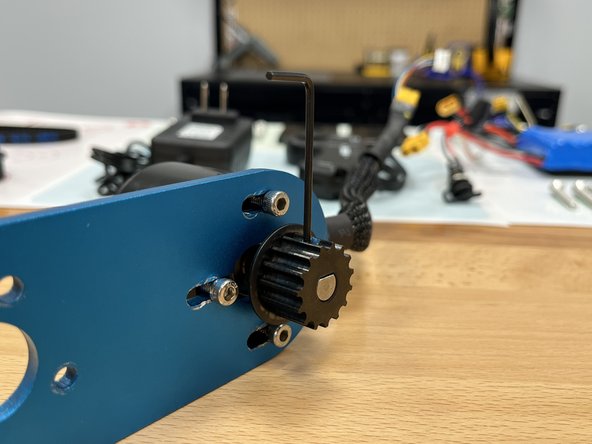
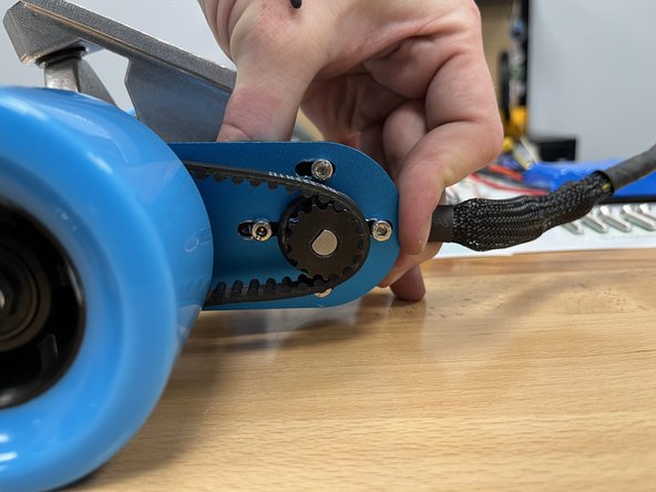
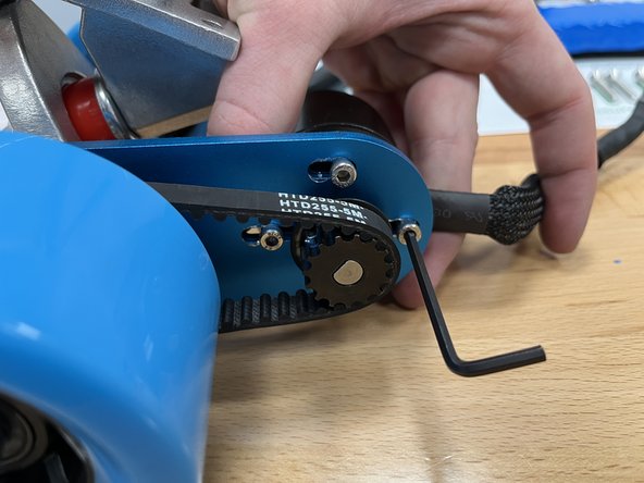
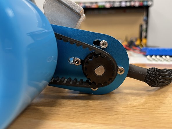
Now its time to tension the belt! Pull back (or to the right) on the motor to apply tension to the belt
-
Once the bolt heads are almost to the rear of the slots, tighten one of the bolts
-
You can then let go of the motor and tighten the other 3 bolts
-
-
-
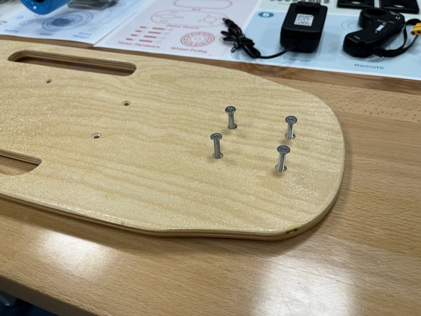
Gather the deck, risers, and truck hardware from section 4
-
Place 4 truck bolts through the front holes in the deck
-
Flip the deck over and add a riser as shown in the photo (note the extra holes towards the left in the photo)
-
Place the front truck from section 2 onto the bolts with the locknut facing forwards
-
-
-
Add the locknuts to the bolt
-
Tighten all 4 locknuts to secure the truck
-
-
-
Flip the deck over and place the 4 other bolts through the rear truck holes
-
Add a riser as shown in the photo (note the extra holes towards the right in the photo)
-
Add the rear truck from section 1 to the bolts, make sure the motor is facing inwards
-
-
-
Secure the rear truck by adding the 4 locknuts to the bolts and tightening
-
-
-
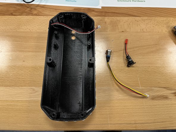
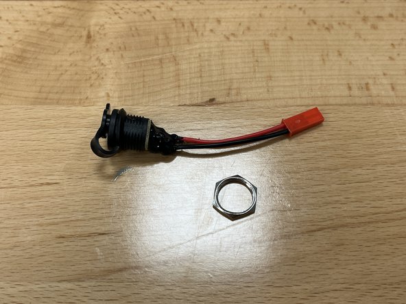
Gather the enclosure, switch, and charge port from section 6
-
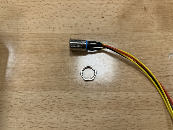
Remove the locknut from the switch
-
-
-
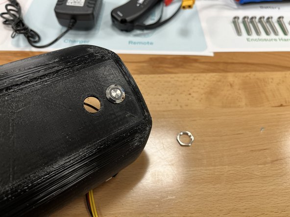
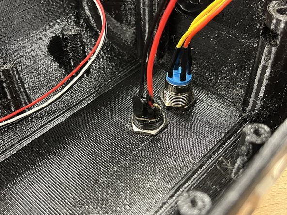
Push the switch through the top hole of the enclosure
-
Secure the switch with the locknut you previously removed
-
-
-
Remove the locknut from the charge port
-
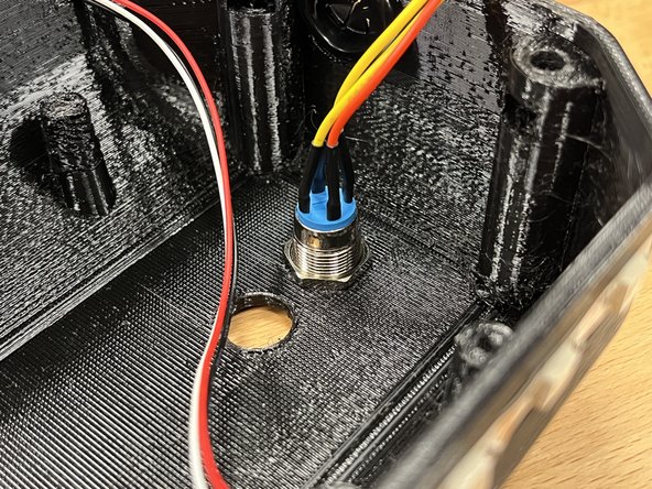
Add the charge port to the second hole
-
Secure it with the locknut you previously removed
-
-
-
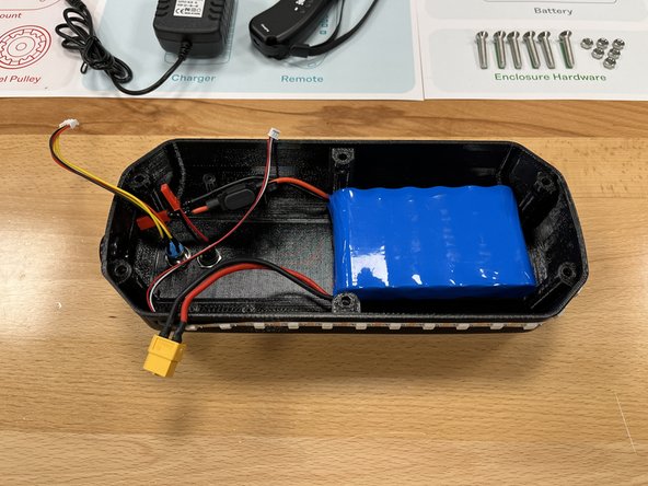
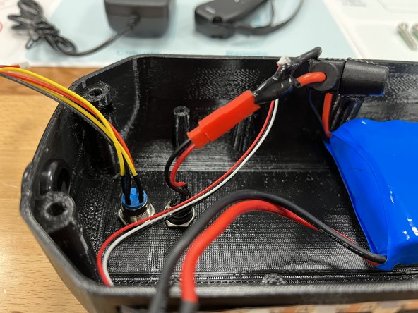
Place the battery inside the enclosure with the wires facing the switch and charge port
-
Connect the charge port to the battery by pushing the two red connectors together
-
-
-
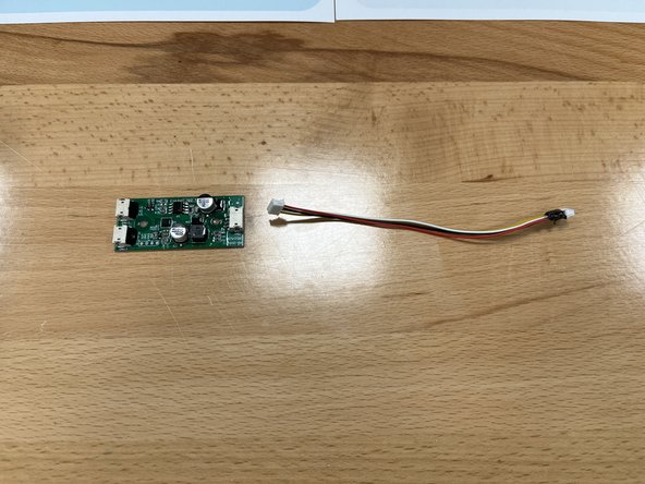
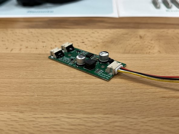
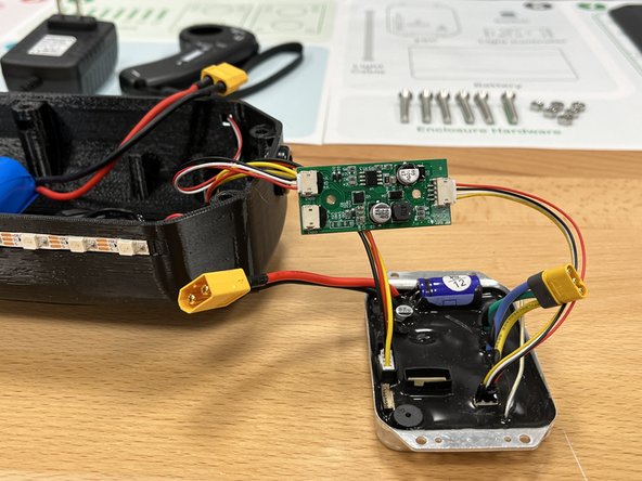
Gather the Light Controller, Light cable, and ESC from Section 6
-
Plug the end without hot glue into the port on the light controller as shown
-
Plug the end with hot glue into Port 3 on the ESC
-
The connector only goes in one way, if it does not go in, do not force it. Flip the connector around and it will fit.
-
-
-
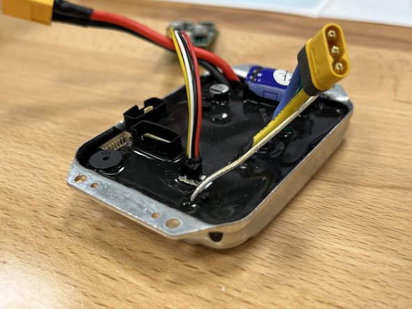
Plug the switch into Port 1, it only goes in one way
-
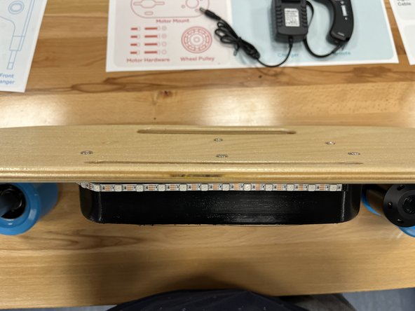
Plug the LED strip into the light controller
-
Connect the battery to the ESC with the large yellow connectors, push them together.
-
-
-
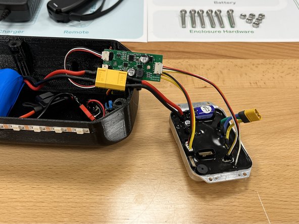
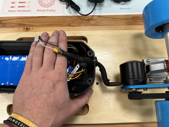
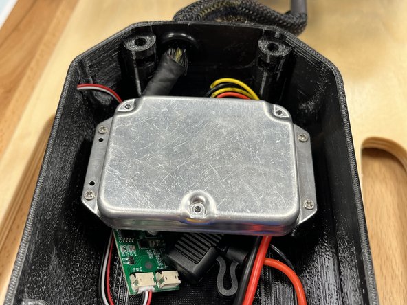
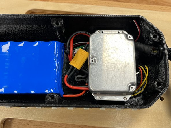
Now its time to connect the motor! Place the light controller into the bottom of the enclosure and then place the ESC inside the enclosure as shown
-
Then place the enclosure on top of the deck
-
-
-
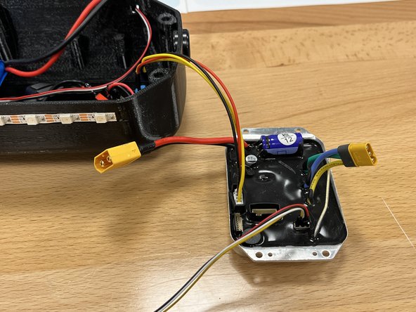
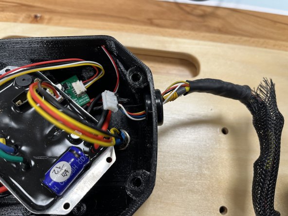
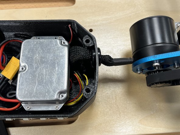
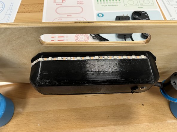
Feed the motor wires (yellow and white connector) through the hole in the enclosure.
-
The photo shows a rubber grommet on the enclosure, we removed them as they were causing issues.
-
-
-
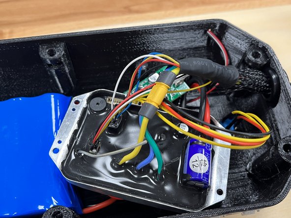
Plug the white connector from the motor into Port 2
-
Plug the yellow connector from the motor to the yellow connector on the ESC
-
-
-
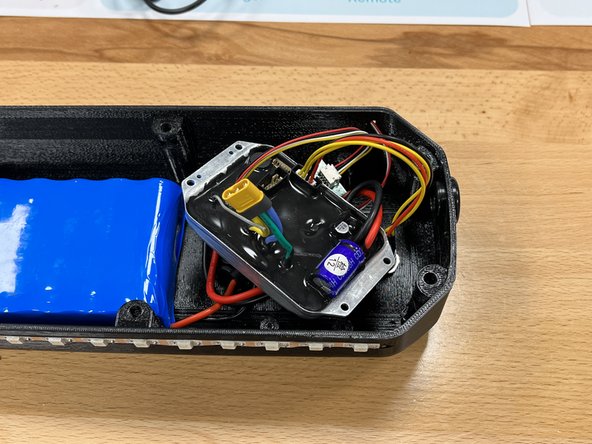
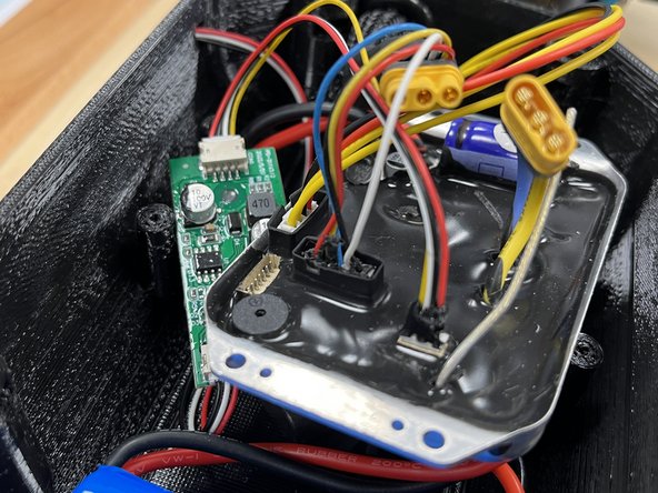
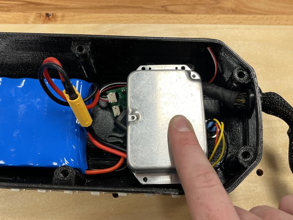
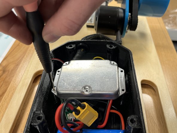
Flip the ESC over and rearrange the wires to fit the ESC onto the 4 plastic tabs
-
Use the 4x phillips screws and the screwdriver to secure the ESC to the enclosure
-
-
-
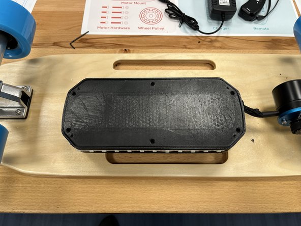
Add the enclosure lid to the enclosure, the logo should be up (if there is one on the lid)
-
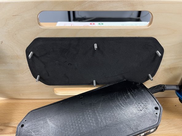
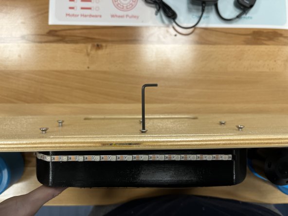
Place the 6 enclosure bolts from section 7 through the deck
-
Add the enclosure gasket from section 6 over the bolts
-
-
-
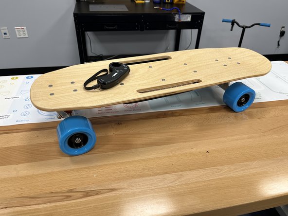
CONGRATULATIONS!! You completed the assembly!!
-
Before you go out and ride, we need to pair the remote to the board.
-
Turn the board on by pressing the power button, you should hear a beep.
-
Then press and hold the power button for 5-10 seconds until you hear another beep, then release the power button.
-
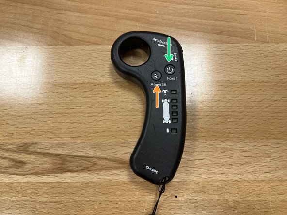
Turn the remote on by pressing the power button
-
Put the remote into pairing mode by pressing both the power and reverse button at the same time. You should hear a beep that it is successfully paired.
-
-
-
Wear a helmet every time you ride!
-
You can limit the top speed of the board by pressing the power button multiple times. This will change one of four status lights, the bottom light indicates a 4mph top speed, 2nd: 8mph, 3rd: 12mph, Top: 15mph. Make sure you start in the bottom 4mph mode.
-
Cancel: I did not complete this guide.
One other person completed this guide.
