-
-
Your ESC will need to utilize RailCore's Enclosure system to connect to the battery, this means you'll need to build the compatible printed circuit board.
-
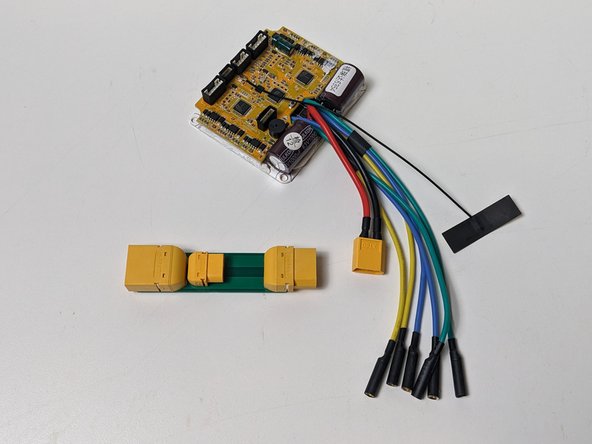
Gather all PCB Components and remove from the bag
-
Locate the small, metal pins located on the XT Connectors.
-
Snap off these metal pins by squeezing with pliers and bending them (they will snap)
-
-
-
Now that the connectors no longer have pins, it's now time to solder them to the PCB.
-
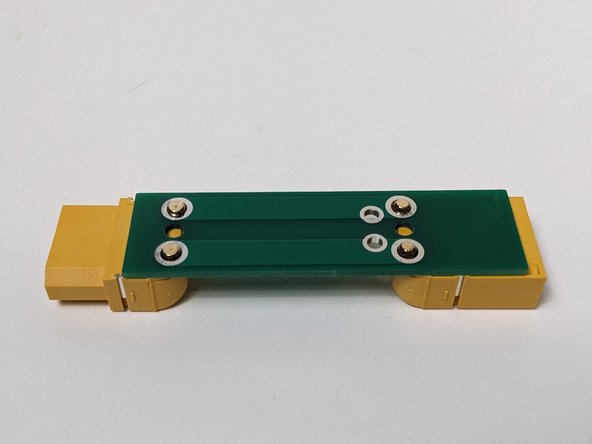
Gather your smaller XT60 Connector and align it with the holes in the middle of the PCB, with the port facing the middle. (Shown in photo)
-
The most important part of this step is that the connector lay flush with the PCB. There shouldn't be any variation in space between the connector and the PCB.
-
Use caution and care when using or operating around a Soldering Iron, as it can easily burn or cause harm.
-
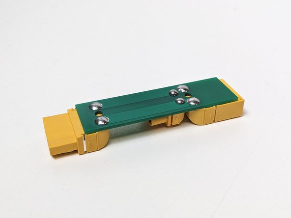
Solder the XT60 to the underside of the PCB to attach it permanently.
-
Solder points should have a round, bubble holding down the connectors. Any excess solder will prevent the PCB from sitting flush within the rail.
-
-
-
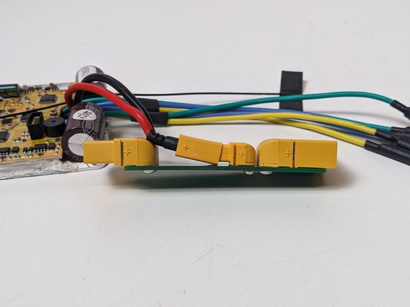
Now that you have your main ESC Port soldered onto the PCB, It's time to solder the battery connectors.
-
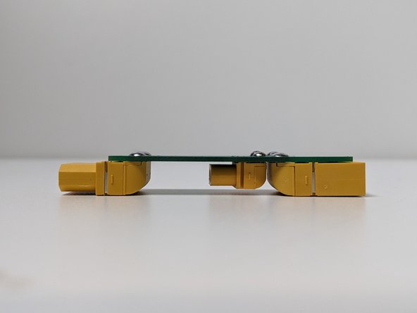
Align your plugs to be flush and parallel with the PCB. With the male connector on the shorter end and the female closest to your XT60 connector.
-
Solder the XT90 to the PCB, ensuring that the ports are stable and aligned properly.
-
Set your PCB aside as we continue to assemble your ESC.
-
-
-
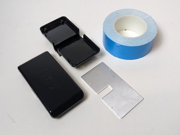
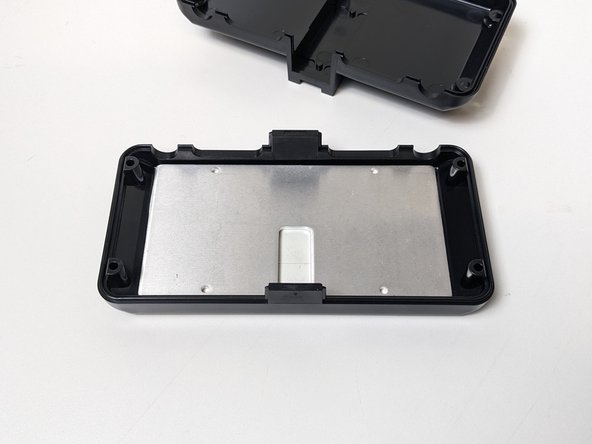
Grab your ESC Enclosure (Top & Bottom), Metal Heatsink, and Thermal Tape.
-
A heatsink is a device or substance for absorbing excessive or unwanted heat. In this case, (no pun intended) we're using these metal plates to absorb the heat of. the ESC.
-
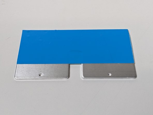
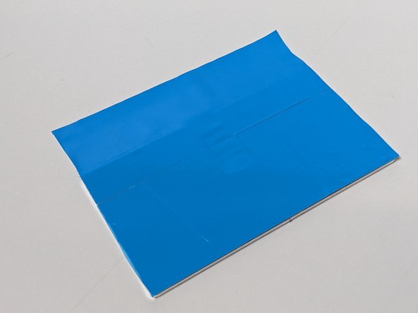
Assure the heatsink is clean and dry. Place a strip of thermal tape over the entirety of one side of the heatsink.
-
Continued in next step
-
-
-
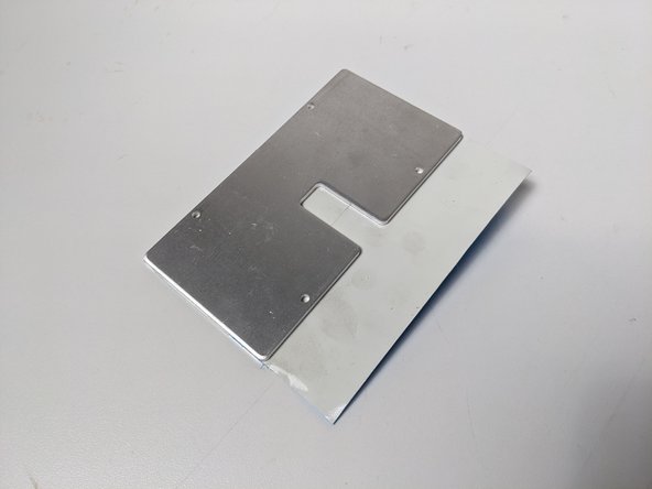
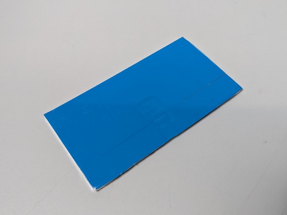
Trim the excess thermal tape and place aside (you can use the excess later if you're careful)
-
No need to trim on the Heatsink's cut-out. A regular rectangle shape is perfect.
-
Peel off the thermal tape's backing and install the heatsink into the TOP of the ESC enclosure by pressing firmly on the heatsinks 4 corners.
-
Make sure you're installing the heatsink on the correct side of the case and it is centered, as to not have a gap between the sink and the casing.
-
-
-
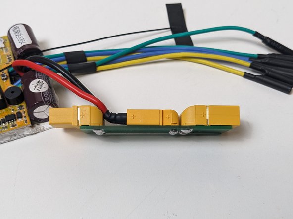
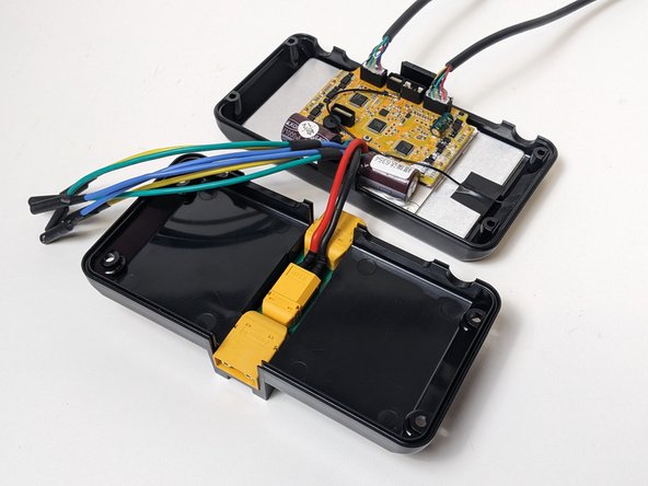
Gather an ESC and your finished PCB. It's now time to connect them.
-
Align the ESC's XT60 Connector with the PCB's. You'll notice that it does not appear to have enough room to connect these two ports...
-
While pushing the connectors together, you can push down to bend the ESC cables to fit into the space between the XT90's.
-
Do not push too hard! This connection while taking some force, should not come close to breaking either the PCB, ESC or connectors.
-
-
-
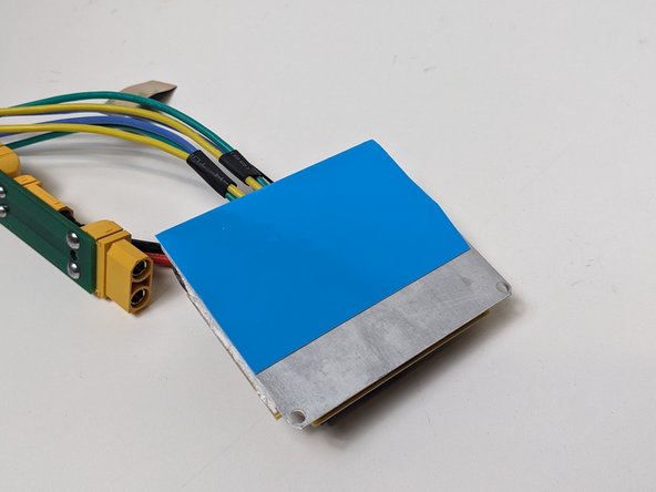
Add thermal tape to cover the entire backside of the ESC. (Here's where you can use that excess material!)
-
Trim the borders for minimal excess.
-
Align the ESC with the Heatsink. Your cables should be sprouting from the enclosure side with NO CABLE PORTS. Your capacitors should not be near the openings of the enclosure.
-
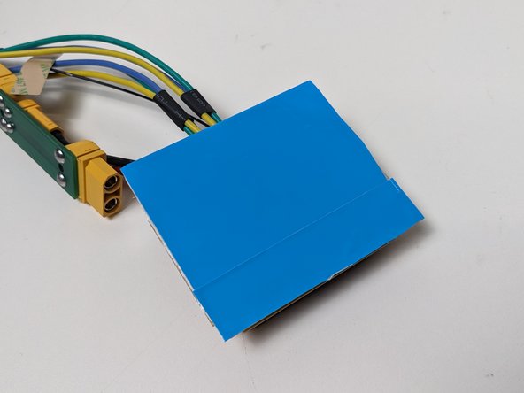
Remove the thermal tape's backing and press down on the the corners to install in the same fashion you aligned it.
-
Once you install anything with thermal tape, it is difficult to adjust. Measure/align twice to ensure you only have to do it once.
-
-
-
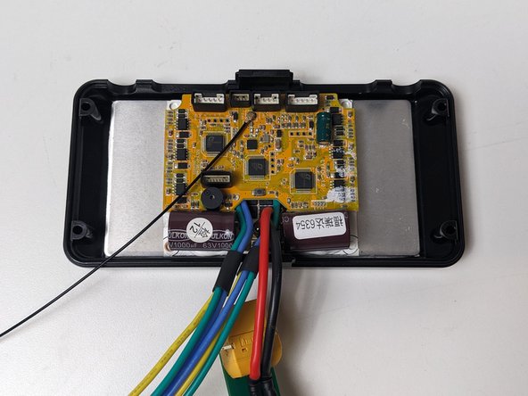
Locate the remote's receiver, which is a small black wire with a black rectangle sticker at the end of it.
-
The ESC Enclosure should have the cables coming out on the side closest to you. The side with cut-outs should be facing away from you.
-
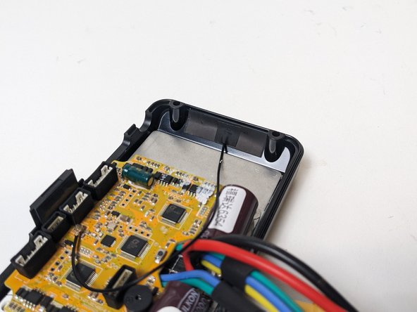
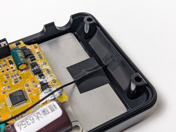
Peel the sticker backing off and install it on the right side of the enclosure casing. Do not let it hang off the edge or have any sharp creases.
-
Once installed, cover the receiver cable with a small piece of electrical tape to secure it down.
-
-
-
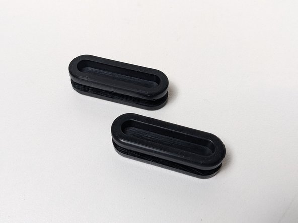
Grab two of the rubber cable gaskets.
-
Cut a line down the middle of the recessed part, making a slit for the cables to come through.
-
Be careful not to cut the entire thing! Only a slit is needed, not hollowing it out.
-
Set these aside for now, you'll need them soon.
-
-
-
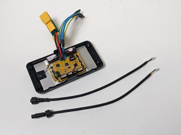
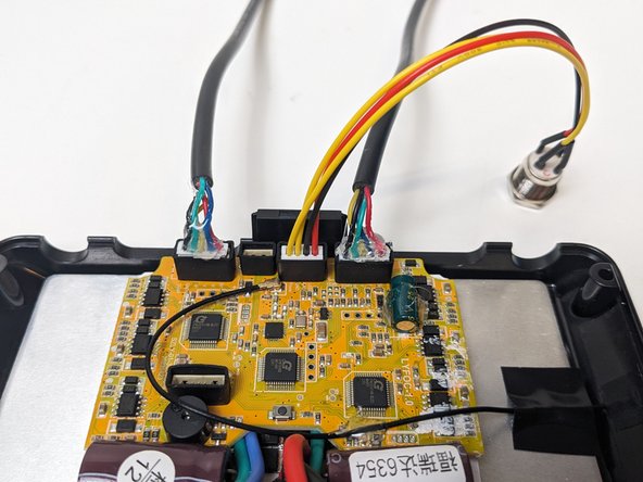
Grab your ESC and 2 motor sensor cables.
-
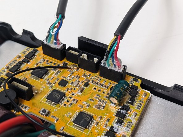
Plug your motor sensor cables into the outer ports on the port-side of your ESC.
-
-
-
Now it's time to use Hot Glue. Grab your hot glue gun and heat it up.
-
Use caution and care when using or operating around a Hot Glue Gun, as it can easily burn you or leak Hot Glue onto other materials or yourself.
-
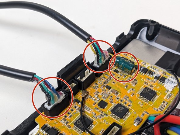
Hot Glue the sensor cable wires to it's port, this will ensure the cables do not have loose connections.
-
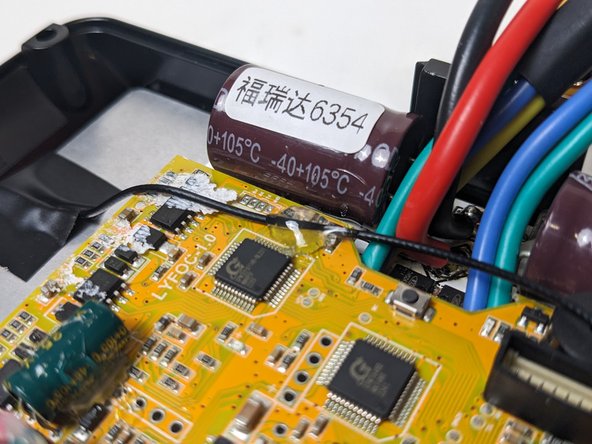
Add Hot Glue to the small green capacitor shown in the photo.
-
Hot Glue the receiver’s cable to the ESC/Main Capacitor to secure it down. You may need to hold it's position while the glue dries.
-
We add Hot Glue to these components to both hold them in place and protect them against potential damage or shifts caused by riding vibrations.
-
-
-
Gather your ESC Enclosure Base, and ESC, It's time to test fit your ESC's PCB into the enclosure's Rail.
-
The Xt90's being flush to the bottom of the enclosure is important, or else connecting batteries will become difficult.
-
Identify the appropriate tabs on the Enclosure Base with the holes on the PCB.
-
The Female XT90 plug should be away from the side with cable openings. (Refer to photos)
-
Push the XT90 onto the appropriate tabs to make the plugs flush to the bottom of the enclosure
-
-
-
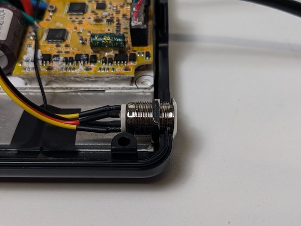
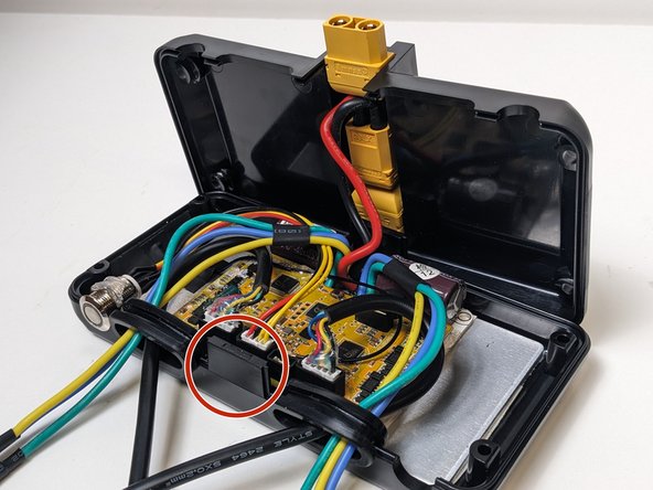
Grab your switch, it's now time to plug-in and install it.
-
Plug the switch into the compatible port, between the two sensor cables.
-
Back the switches screw-back off to fit the thickness of the enclosure. (Shown in photo)
-
Add some hot glue to behind the screw to secure it in place.
-
-
-
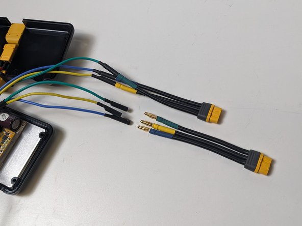
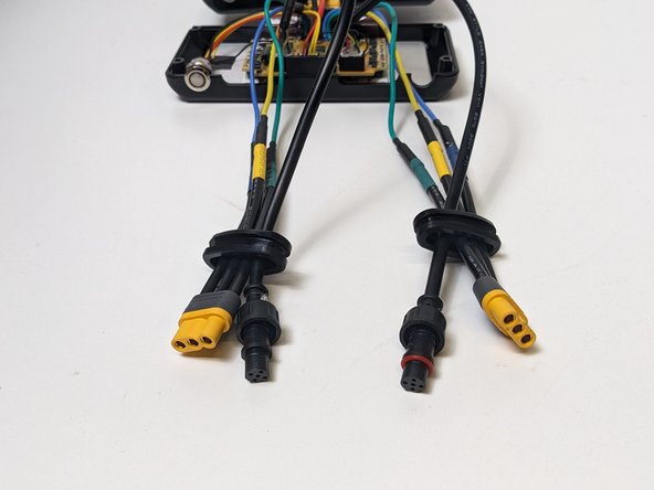
Gather 2 motor cable adaptors, and the Rubber Cable Gaskets that were cut in step 9.
-
Connect the cable adaptors to the matching color bullet connector, be careful not to cross sides.
-
Bullet connectors are the single pin connectors on the colored-cable end. The yellow connectors are MR60 plugs.
-
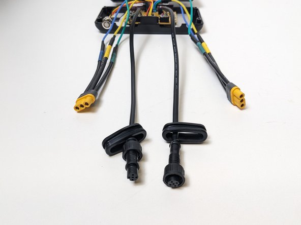
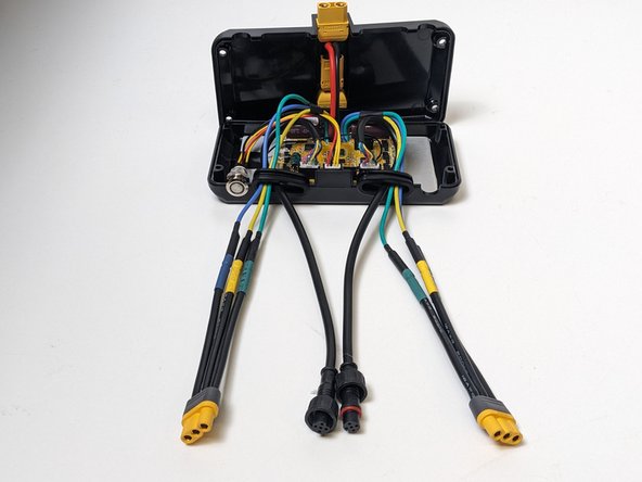
Now it's time to route the cables through the rubber gaskets.
-
First, route the sensor cables through and push to the center-most side. Then route the MR60 through.
-
Make sure the cables are not tangled, crossed, or taking up excess space. Space within the enclosure is minimal and cable management is important.
-
-
-
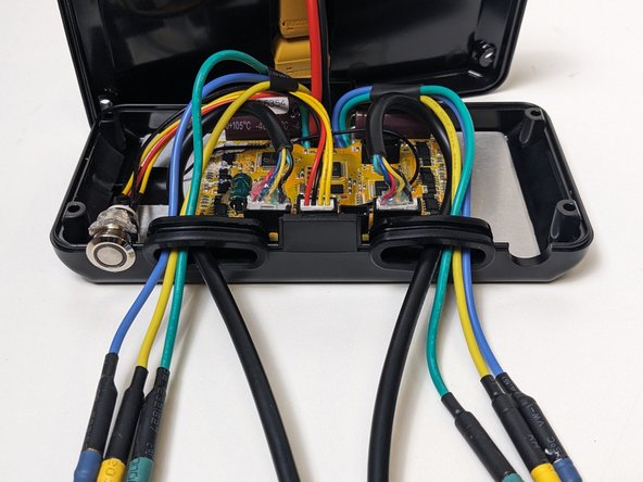
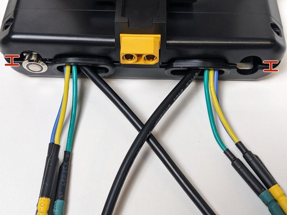
Slide the Rubber Cable Gaskets up the cables to the cable cutouts on the ESC enclosure.
-
Tuck and pull the cables through to make space in the enclosure.
-
The Goal here is to ensure that now cables will be crushed, crimped, or broken by the enclosure closing.
-
Be sure not to have cables in any of the 4 corners. Screws will be going through these holes with no room to spare.
-
-
-
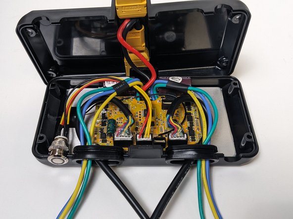
With your wire's properly tucked. and managed, it's time to connect both sides of the ESC's enclosure.
-
Lift the bottom case (side with PCB) by the corners and lower the case evenly on all corners.
-
Make sure the enclosure tab's are aligned and within the designated area. Keep an eye on maintaining the position of the rubber gaskets and switch.
-
Do not forcefully push down! There should be some resistance, but not enough to break anything or to cause difficulty.
-
-
-
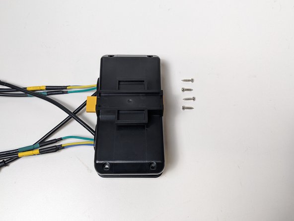
Gather 4 of your enclosure screws, it's time to connect both sides!
-
You're going to add the screws in a two step process.
-
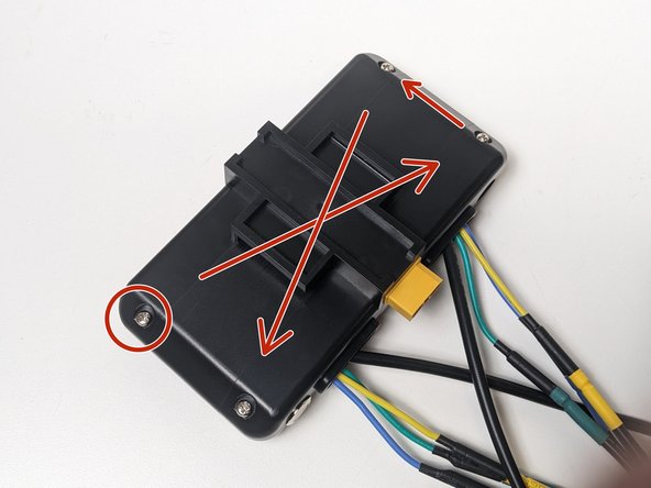
First, screw each corner in half-way, working in a diagonal pattern.
-
Then repeat the same pattern to tighten the screws fully.
-
Do not over-tighten any screws! Over tightening could lead to broken screws and inoperable ESC enclosures.
-
-
-
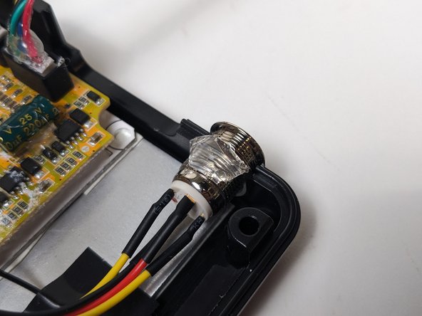
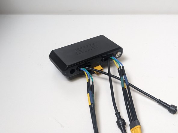
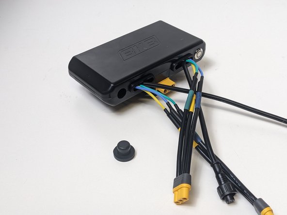
Flip your ESC over and grab your rubber stopper.
-
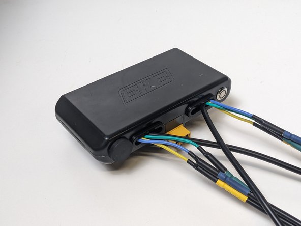
Work your rubber stopper into the round port opposite of the ESC's switch.
-
You've just assembled your board's ESC! Now it's time to test by plugging into a battery and connecting a remote!
-
Be sure to wear helmets and protective gear whenever riding or operating your vehicle in any capacity.
-