Tools
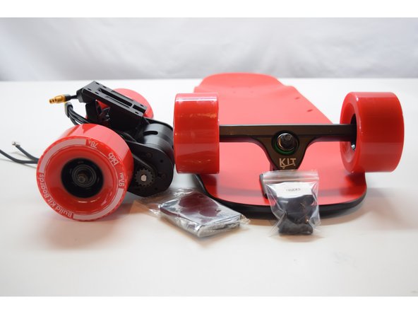
Parts
- 31" Tayto Deck
- 97mm Skateboard Wheels
- Truck Hanger × 2
- Truck Baseplate wow × 2
- 1/4in Riser × 2
- Bearing Set
- Truck Hardware Set
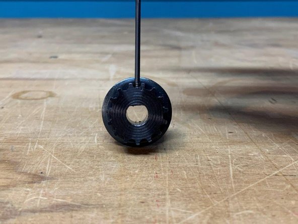
- Wheel Pulley
- Motor Pulley
- 265m-12mm Belt
- Motor Mount
- Motor Hardware Set
- 6354 Motor
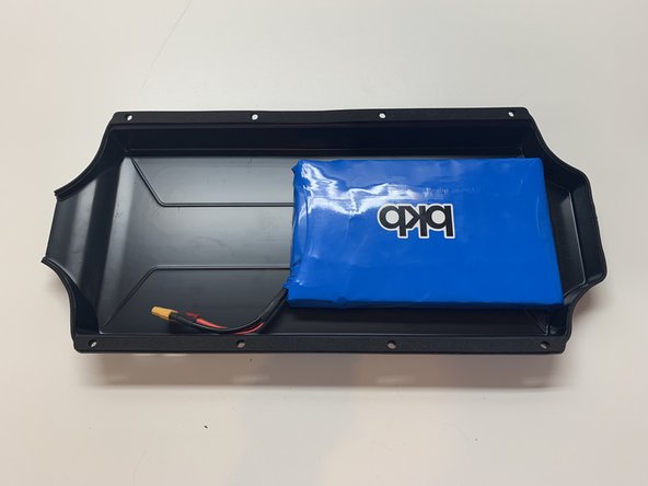
- Tayto Enclosure
- Enclosure Hardware Set
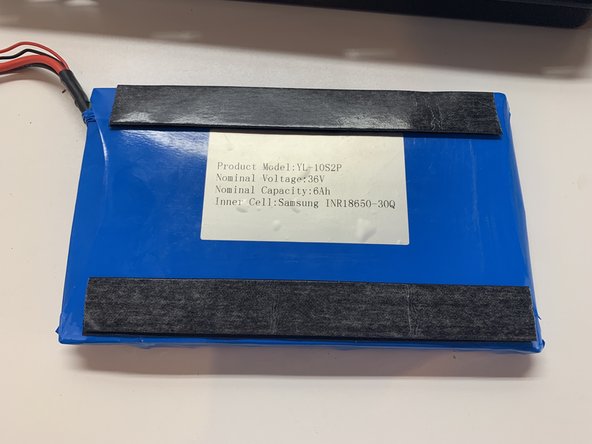
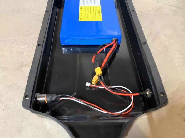
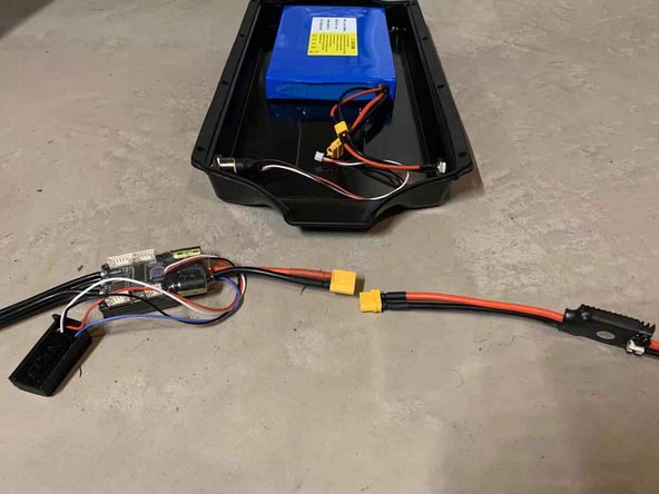
- 10s2p Battery
- 10s3a Charger
- Single VESC ESC
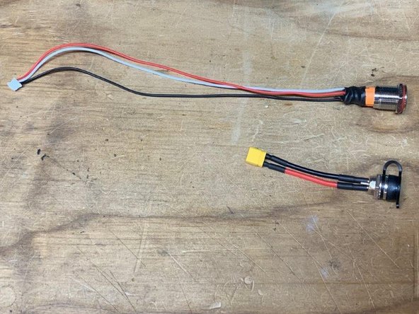
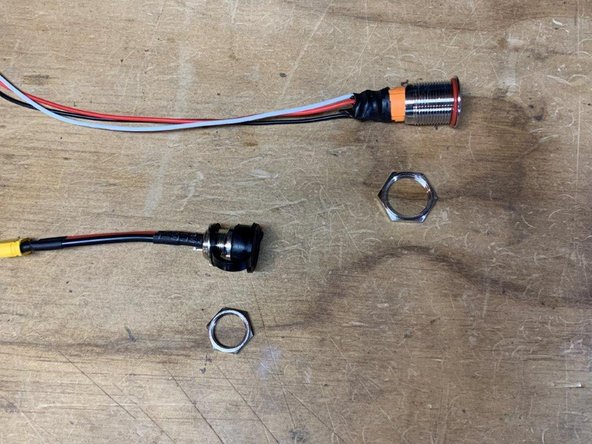
- Anti-Spark Switch
- VX1 Remote
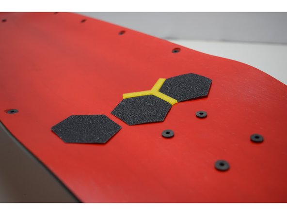
- Griptape Hexagons
-
-
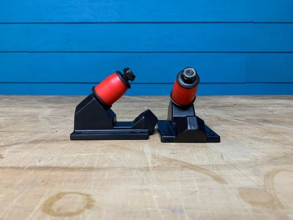
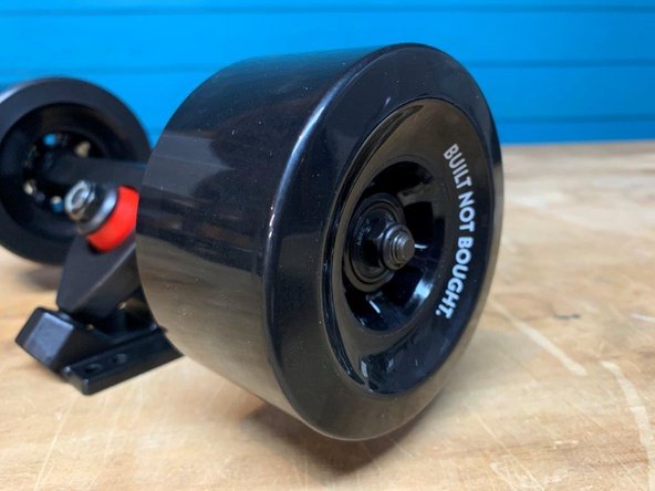
Gather the wheels and bearings
-
Place one bearing in the wheel
-
Flip it over and place a silver spacer on top of the bearing.
-
-
-
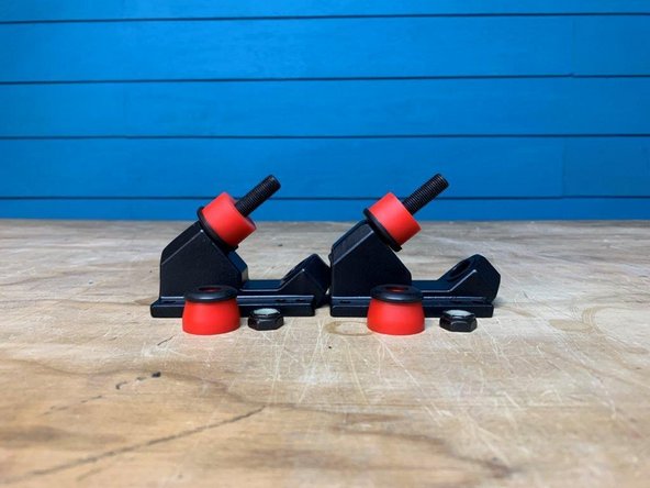
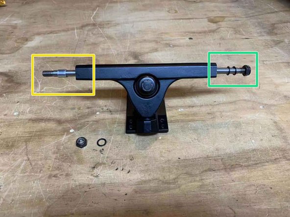
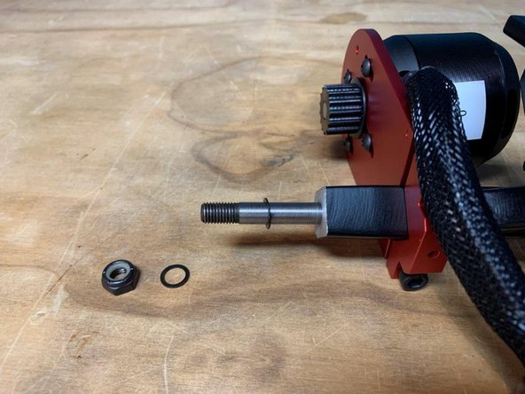
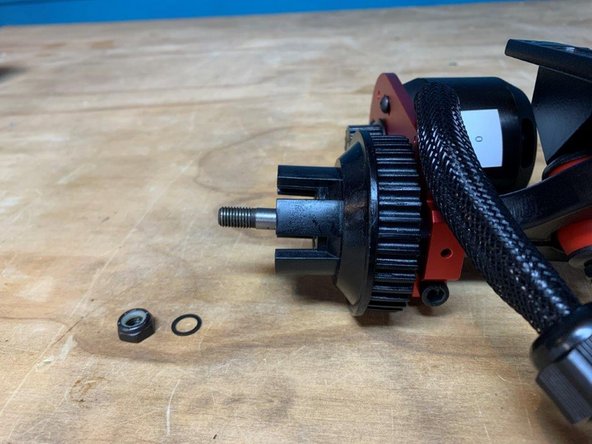
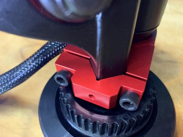
Place the bushing and washer back on and tighten the locknut
-
If your having trouble getting the locknut to start threading, make sure the hanger is pushed all the way into the base of the baseplate (where the hanger comes to a rounded point). You can also apply pressure down on the truck to compress the bushings
-
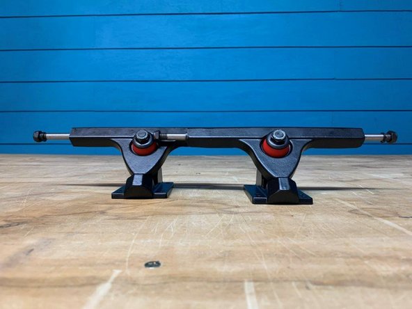
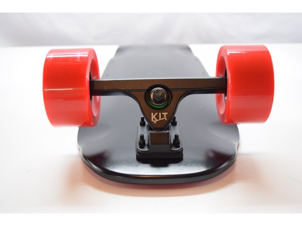
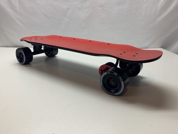
Repeat this process to complete two trucks
-
-
-
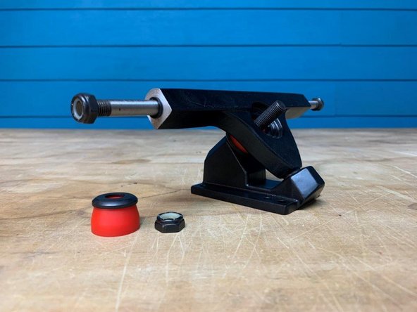
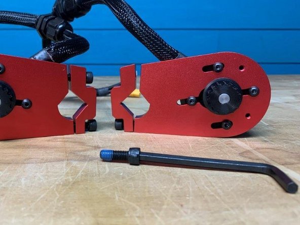
Gather the front truck, two wheels, and T-Tool
-
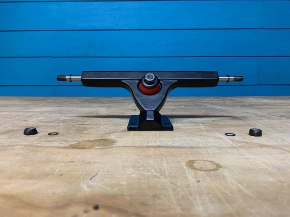
Remove one locknut and one washer from each side of the truck. Make sure there is still one washer on the truck
-
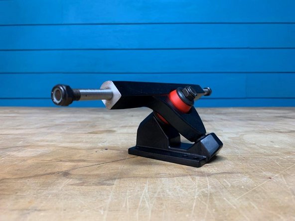
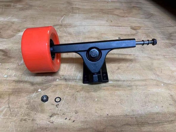
Place one wheel on each side with the letters facing outward
-
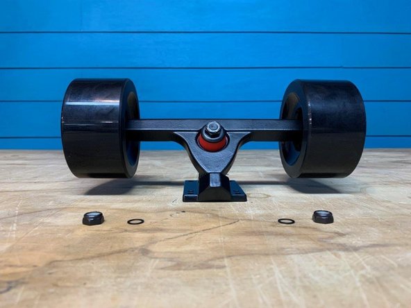
Add the washer and locknut back onto the truck. From inside to outside the components should be arranged: washer, wheel, washer, locknut
-
Repeat on the other side to secure both wheels
-
-
-
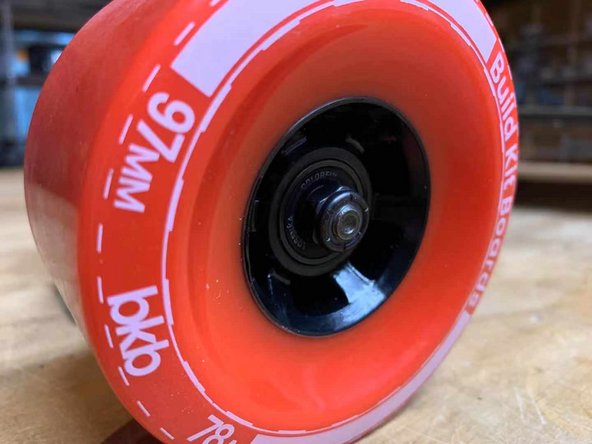
It is very important not to over tighten the locknuts. It will create much more rolling resistance
-
Tighten the lock nuts until they touch the bearing. Then loosen the lock nuts ~ half a turn. You should be able to very lightly move the wheel laterally on the axle. If there is no movement it is too tight, and if the wheel can slide the lock nuts are too loose
-
-
-
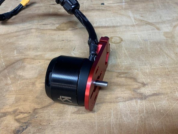
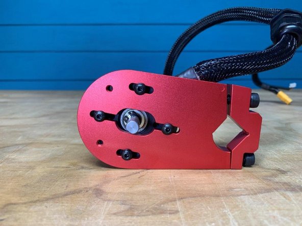
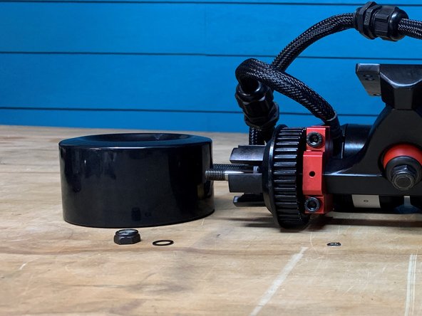
Gather the motor mount, motor, motor hardware, loctite, and allen wrenches
-
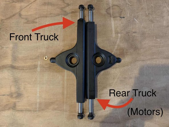
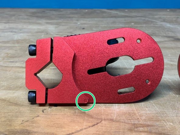
One motor mount has a dot cut out on each side. This is the left motor mount and will go on the left side of the truck (later on). If your motor mount does NOT have these marks, it is a right motor mount, and will be installed on the right side of the truck
-
-
-
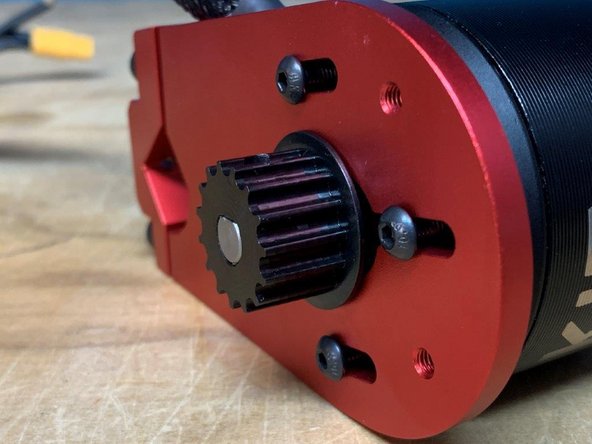
Place the motor mount on top of the motor with the wires oriented as shown
-
Place 3-4 drops of loctite on each bolt and fasten the motor mount and motor together
-
Do NOT tighten the bolts all the way. You should be able to move the motor back in forth in the channels. This will allow us to tension the belts later on
-
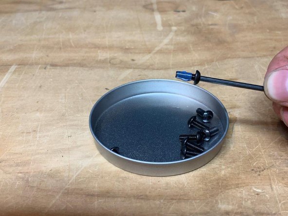
Tip: use the bearing set lid to make sure bolts dont roll away
-
-
-
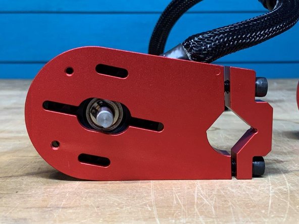
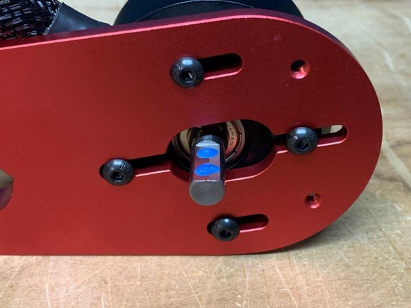
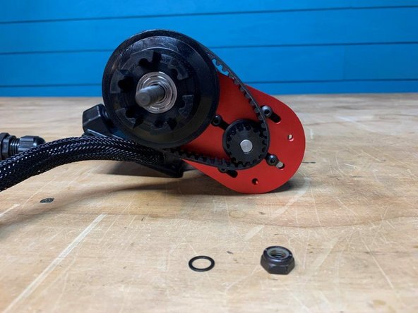
There is an extra spacer included in the tool kit. This will be used on the rear truck on the side that does not get a motor mount.
-
If your motor mount does NOT have a dot on each side, place the spacer on the Green (right) side
-
If the motor mount HAS a dot on each side, place the spacer on the YELLOW (left) side
-
-
-
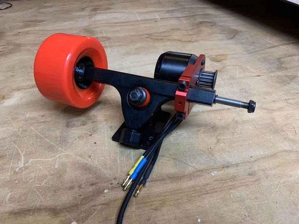
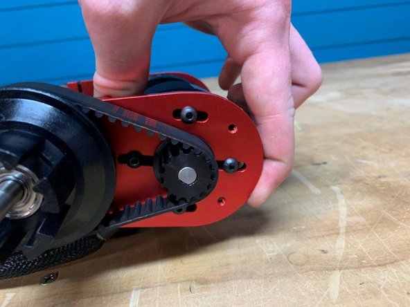
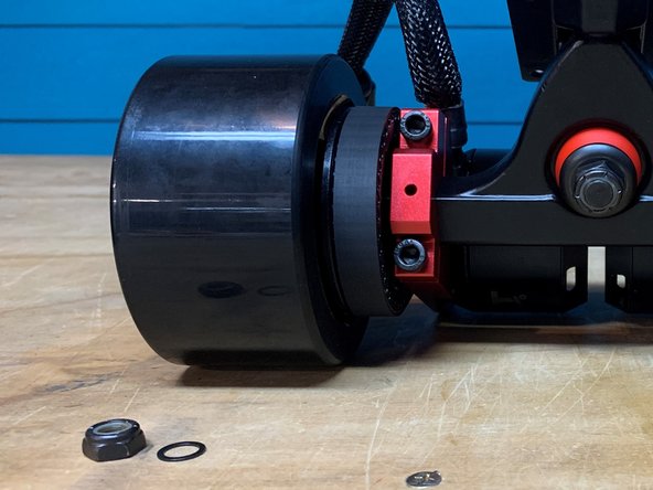
Slide the wheel onto the truck AND secure it with the washer and locknut you just took of
-
Place the motor mount spacer (green, blue, or black) in between the motor mount and wheel pulley. The wheel should not be able to move laterally on the truck
-
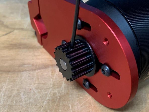
Tighten the bolts on the motor mount A QUARTER TURN at a time. So, tighten the top bolt a quarter turn, bottom bolt a quarter turn, and repeat until the mount is tight. This will make sure you have even pressure on both bolts, there should be an equal gap between the top and bottom of the motor mount (last photo)
-
When done, remove the motor mount spacer
-
-
-
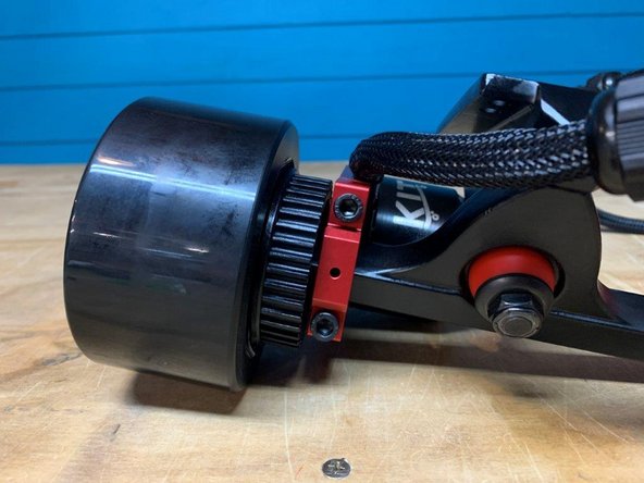
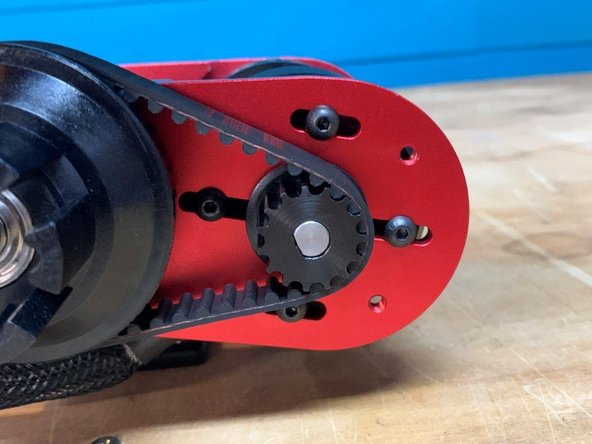
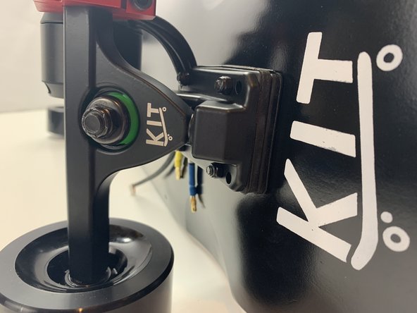
Slide the motor outwards from the truck to put tension on the belt
-
Tighten all four bolts
-
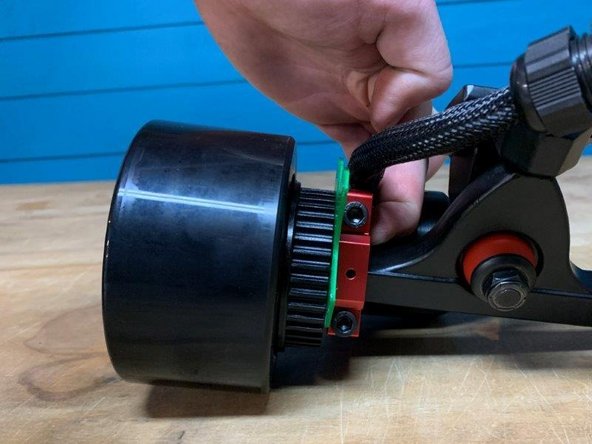
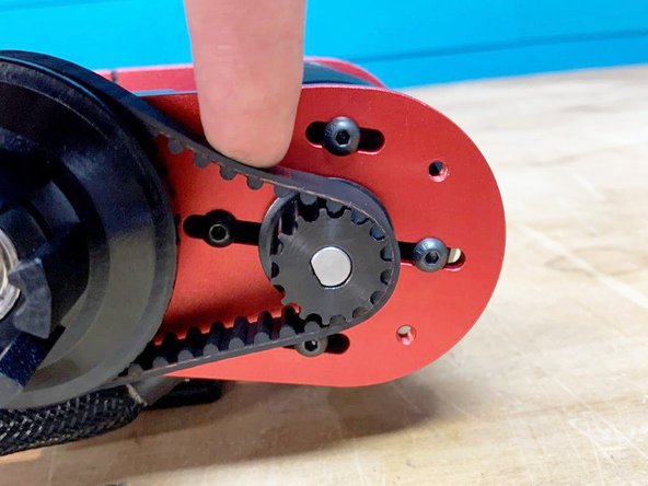
Put a small amount of pressure downwards on the belt. It should deflect slightly as shown in the 3rd photo
-
If the belt deflects more than you need more tension, so loosen the bolts to readjust
-
If the belt barely deflects, or dosnt at all, they are too tight. Loosen the screws to readjust.
-
Tighten the bolts when done adjusting until you find the proper belt tension. It is always better to have loose belts compared to tight ones
-
-
-
WARNINGS!
-
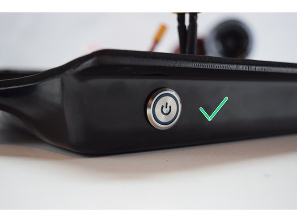
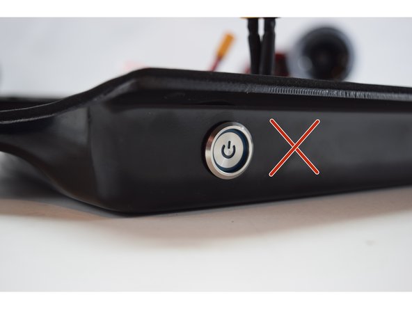
VERY IMPORTANT: Do NOT leave the switch in the on position when not using the board! It will completely drain the battery (and make in unusable). Remember to turn the board off after every ride.
-
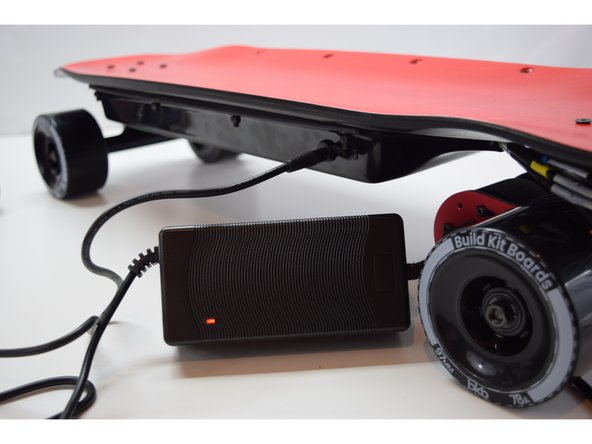
If you are not going to use the board for 2 weeks or more, be sure to charge the battery to 36V and unplug it.
-
ALWAYS WEAR A HELMET! THEY SAVE LIVES. DONT WEAR IT FOR YOU, WEAR IT FOR YOUR FAMILY.
-
Electric skateboarding is a very fun and rewarding sport. But, everyone has fallen off their board at some point. It's not a matter of if it will happen, but when it will happen. Please wear at least a helmet and always ride within your comfort zone
-
Treat the board with respect! It is a vehicle after all. Do NOT drop the board from a vertical position to set it down as it put a lot of stress on the enclosure. Give the board a good once over before every ride to make sure bolts are tight and things look normal.
-
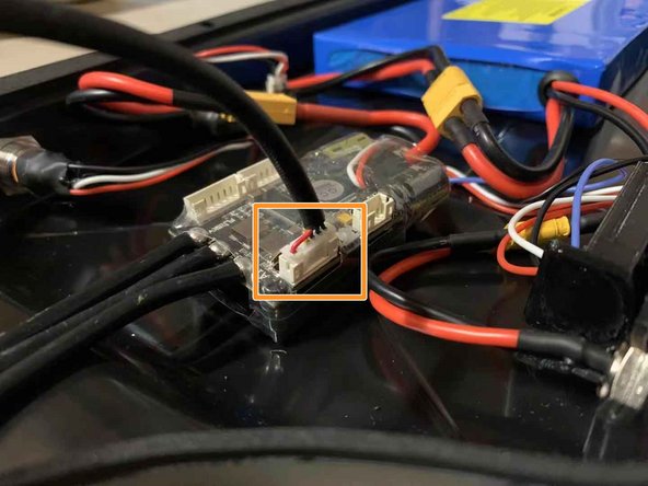
NEVER CHANGE THE FIRMWARE ON THE VESC! IF YOU ARE HAVING AN ISSUE REACH OUT TO SUPPORT BEFORE CHANGING ANY SETTINGS ON THE VESC!
-
-
-
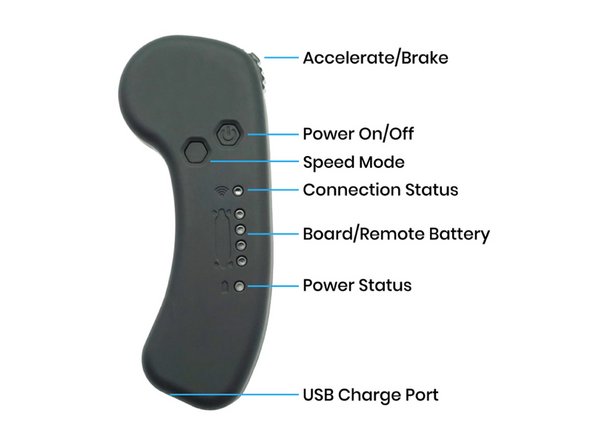
Its time to ride! The remote has three acceleration modes
-
Red = full acceleration
-
Yellow = medium acceleration
-
Green = low acceleration (beginner)
-
When riding for the first time make sure you are in the green mode. Then slowly work you way up to red. THE BOARD HAS MORE POWER THAN YOU REALIZE.
-
ALWAYS RESPECT THE BOARD AND RIDE WITHIN YOUR LIMITS. OBEY ALL TRAFFIC LAWS AND WEAR A HELMET.
-