
Tools
Parts
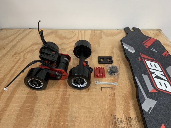
- 43in Tru-Flex Deck
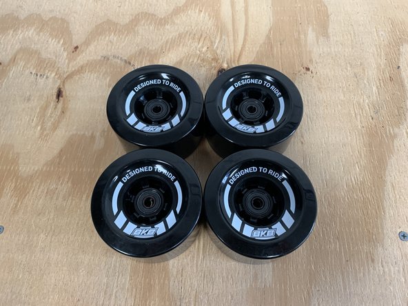
- 97mm Skateboard Wheels × 4
- Truck Hanger × 2
- Truck Baseplate wow × 2
- 1/4in Riser × 2
- Bearing Set
- Motor Pulley × 2
- Truck Hardware Set
- Motor Hardware Set
- Enclosure Hardware Set
- Wheel Pulley × 2
- 315M Belt × 2
- Motor Mount × 2
- 6354 Motor × 2
- Duo Enclosure
- Battery
- GX12 Charge Port
- Charger
- BKB Xenith
- BKB Voyager
- Top Rails × 4
-
-
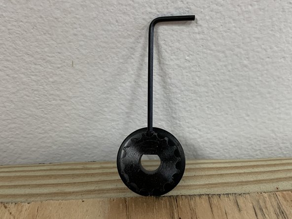
Gather the wheels, bearings, T Tool, and one truck hanger
-
Use the T tool to remove the locknut and washers from one side of the truck
-
Place one bearing onto the truck with the black covered side towards the center
-
-
-
Push a wheel onto the bearing and truck to install it
-
Place one bearing onto the truck with the black covered side towards the center. Then add a silver spacer onto the truck
-
Push the wheel onto the bearing and truck to install it
-
-
-
Repeat the bearing insertion process in the previous step to complete all four wheels
-
-
-
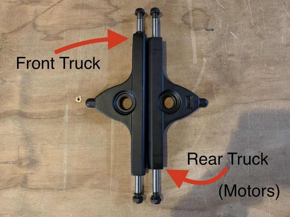
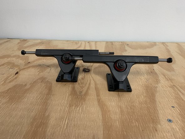
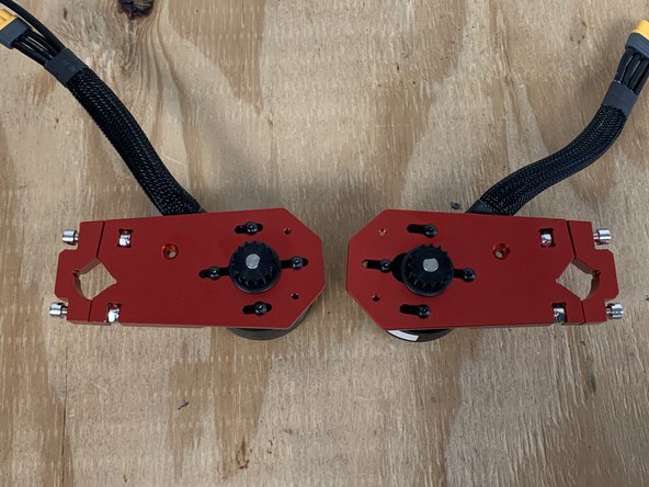
Later on in the tutorial you will need to know the difference between the front and rear truck.
-
The front truck has a wider hanger
-
The rear truck has a shorter hanger to accommodate the gear assembly and wheel pulley
-
IMPORTANT NOTE: If you have the TorqueMonster upgrade/Extended trucks, both front and back hangers are the same lengths.
-
-
-
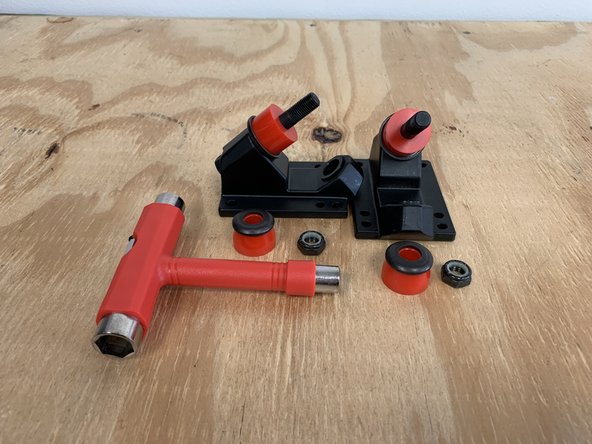
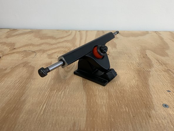
Gather the truck baseplates, truck hangers, and T-Tool
-
Remove the locknut from each baseplate
-
Remove one bushing and washer from each baseplate
-
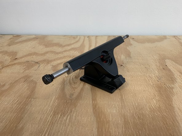
Place a truck hanger in the baseplate with the words facing inward
-
-
-
Place the bushing and washer back on and tighten the locknut
-
If your having trouble getting the locknut to start threading, make sure the hanger is pushed all the way into the base of the baseplate (where the hanger comes to a rounded point). You can also apply pressure down on the truck to compress the bushings ( the squishy red plastic bits) to give yourself more exposed threads to attach the locknut.
-
Repeat this process to complete two trucks
-
-
-
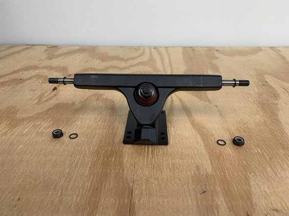
Gather the front truck, two wheels, and T-Tool
-
Remove one locknut and one washer from each side of the truck. Make sure there is still one washer on the truck
-
TorqueMonster/Extended Trucks require a silver spacer between the wheel and hanger for proper fitment.
-
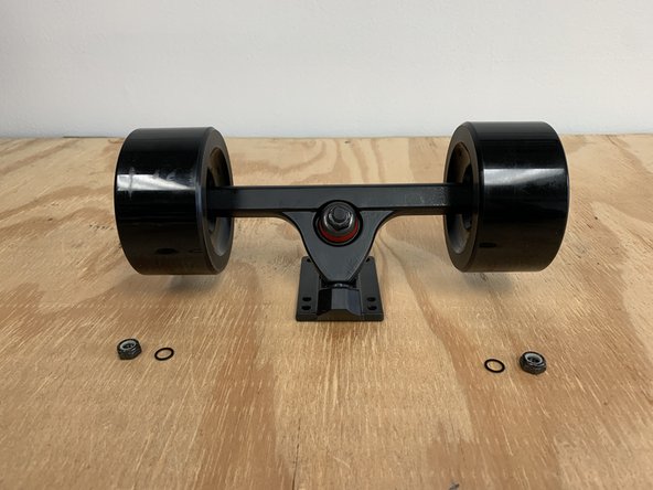
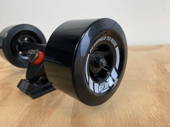
Place one wheel on each side with the letters facing outward
-
Add the washer and locknut back onto the truck. From inside to outside the components should be arranged: washer, wheel, washer, locknut
-
Repeat on the other side to secure both wheels
-
-
-
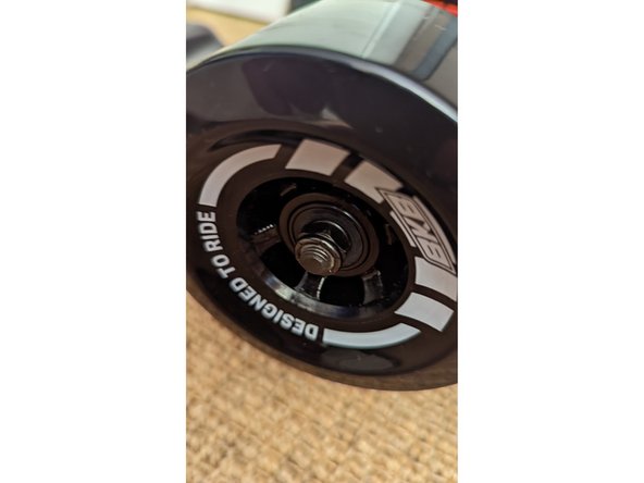
Tighten the lock nuts using the T-tool until they just touch the bearing. Then loosen the lock nuts a quarter turn of the tool. You should be able to move the wheel laterally on the axle by about 1mm.
-
If there is no movement laterally with the wheel on the axle, then the lock nut is too tight causing more friction than necessary.
-
If the wheel can move by 2mm or more the lock nuts are too loose. Loose wheels will cause wobble, uneven wear and lost speed.
-
DO NOT over tighten the locknuts. It will create much more rolling resistance causing lower distance and power for the board, as well as increased time to get to the proper speed.
-
-
-
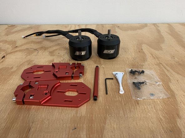
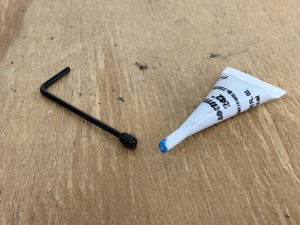
Gather the allen wrench, motors, motor mounts, cross bar, Loctite, and motor hardware.
-
We no longer include the Red Cross bar with the motor mounts. So, do not expect it to be in your package
-
The motor hardware is labeled on the plastic bag for easy identification.
-
One motor mount has a dot cut out on each side. This needs to have the left motor (marked with an 'O' sticker) attached to it.
-
The 'left' motor is when the front of the board is pointing away from you, and the bottom of the board is facing up, this side has the padding on it.
-
One motor should have an 'O' sticker, but if it does not that is okay. You can use either motor and switch the motor direction later if need be
-
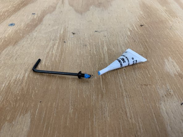
To open the loctite, break off the end cap and then flip it over to puncture a hole in the capsule using the prong on the inside of the cap.
-
If you will be doing this project in multiple stages, please don't proceed unless you are able to commit to a final location for all screws that have loctite applied. The loctite will dry in 24 hours making further assembly more difficult.
-
-
-
Place the motor mount on top of the motor with the wires oriented as shown
-
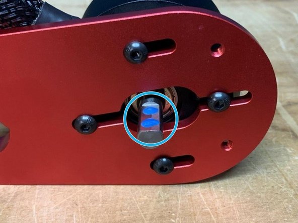
Add a drop of loctite to each motor screw before installing
-
Notice that there is a cut-out on one side of the metal hanger for each motor, the other side is flat. The flat side will face the wheel, and the motors, with be on the "inside" together. Examine the final picture if this is confusing.
-
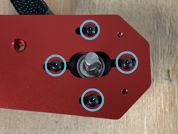
Anytime there is a blue circle in a photo it represents where a drop of loctite needs to be added
-
Install 4 motor screws to attach the motor to the motor mount. For now, only tighten these motor mounts until the screws hold the motor in place. We will tighten these later when the belt is attached.
-
-
-
Repeat this process to attach the other motor to the motor mount
-
Ensure you use Loctite on each bolt
-
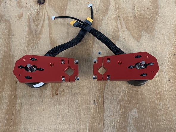
Look closely at the wire positioning. In this picture they are both "up". If yours do not look like the picture, then the motors are mounted incorrectly.
-
-
-
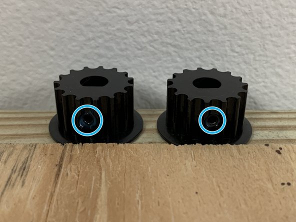
Gather the motor pulleys, 2mm Allen wrench, and Loctite
-
Remove the set screw from the motor pulley
-
Add Loctite to the set screw
-
Reinstall the set screw into the pulley so that it holds on its own.
-
If you turn the set screw in too much to the point it is visible in the center of the shaft hole, it will not slide onto the motor
-
Repeat this process for the other motor pulley
-
-
-
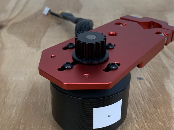
Add two drops of Loctite to each motor shaft on the flat section.
-
Place the motor pulley onto the motor shaft
-
It is designed to be a tight fit and must be aligned. If the motor shaft does not go completely through the motor pulley, use the Allen wrench to loosen the set screw in the motor pulley and try again.
-
Ensure the motor pulley is pushed all the way on the motor shaft.
-
Tighten the set screw on the motor pulley.
-
-
-
Repeat this process to install the motor pulley on the other motor
-
-
-
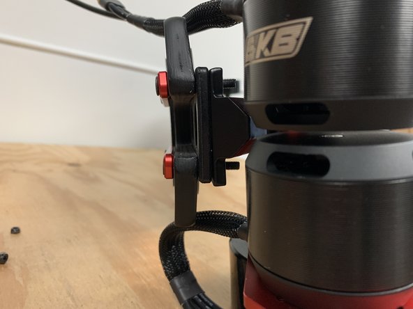
Use the 5mm Allen wrench to loosen the motor mount bolts
-
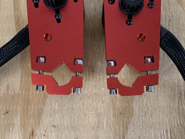
Slide the motor mounts onto the rear truck
-
They should go on the side of the truck with the "protrusion", not the large lock nut.
-
-
-
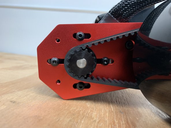
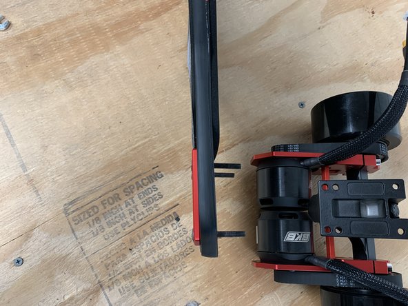
Align the motor mount assembly to the center of the truck. There should be even spacing on both sides of the truck, and the motors should be level with one another.
-
Tighten the bolts on the motor mount evenly. You should turn each bolt 1/4 to 1/2 a turn at a time. Then tighten the other bolt 1/4 to 1/2. This ensures there is even pressure on each bolt
-
There is a gap on the top and bottom in between the clamp and motor mount. This gap should be the same on the top and bottom. If they are different, loosen the bolts and retighten them
-
Since the cross bard is no longer included you will need to install the motor mounts in a different manner. You can align the motor mounts by eye (to the center) and then use the black 3d printed spacer to place between the wheel pulley and motor mount for final alignment.
-
-
-
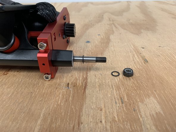
Use the T Tool to remove the locknut and 1x washer from the truck
-
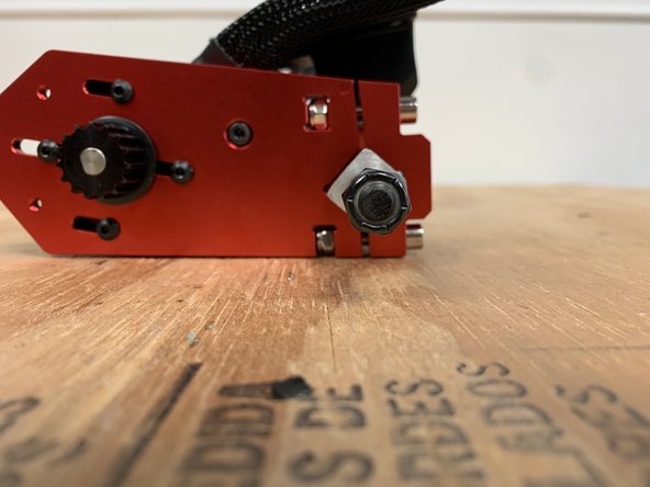
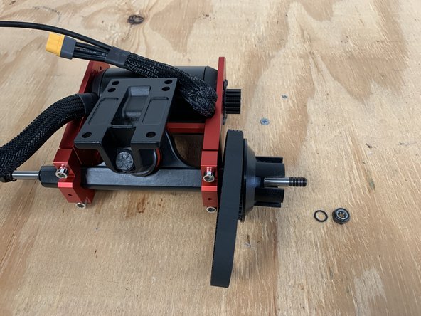
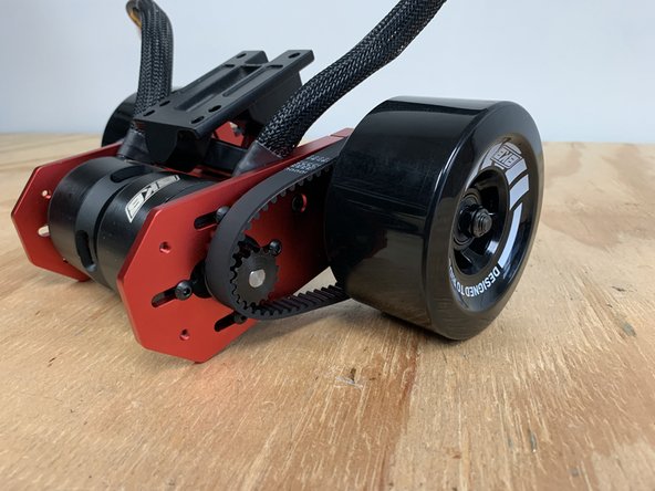
Slide the wheel pulley and belt onto the truck
-
Place the belt over the motor pulley. You will need to slide the motor all the way forward and the four bolts securing the motor will need to be loose to accomplish this
-
-
-
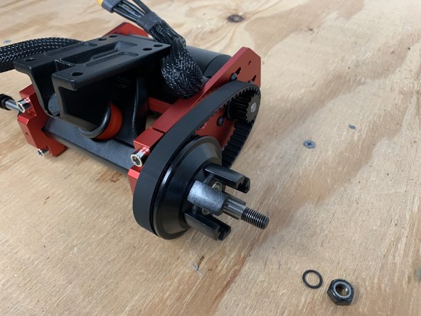
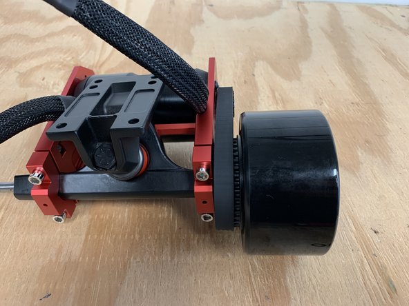
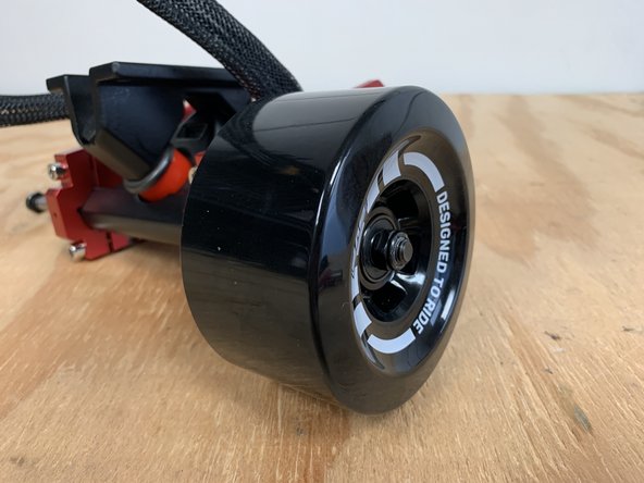
Slide the wheel onto the truck with the words facing outwards
-
Add the washer and locknut back onto the truck. Tighten with the T Tool
-
Do NOT over tighten the locknut. You should be able to move the wheel laterally on the axle back and forth ever so slightly
-
-
-
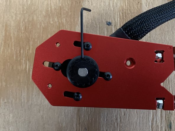
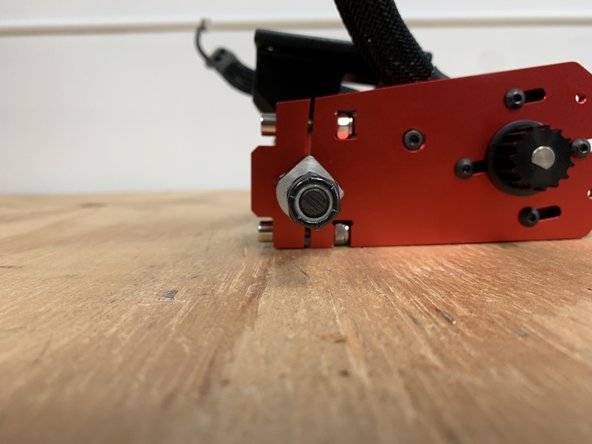
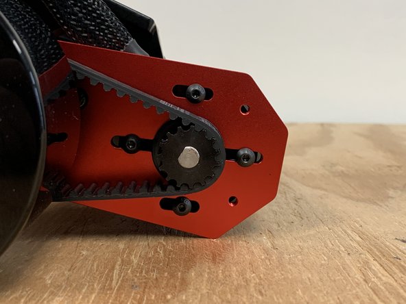
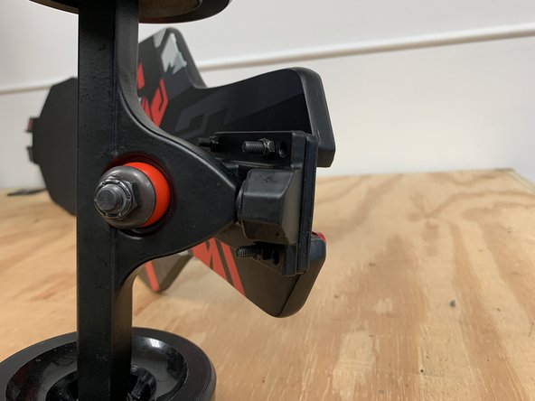
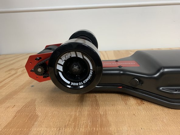
Now it is time to tension the belt. Pull back on the motor until the there is decent tension in the belt
-
While holding tension in the belt with one hand, tighten a bolt to hold the motor in place for the next test.
-
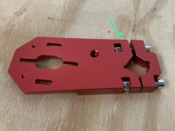
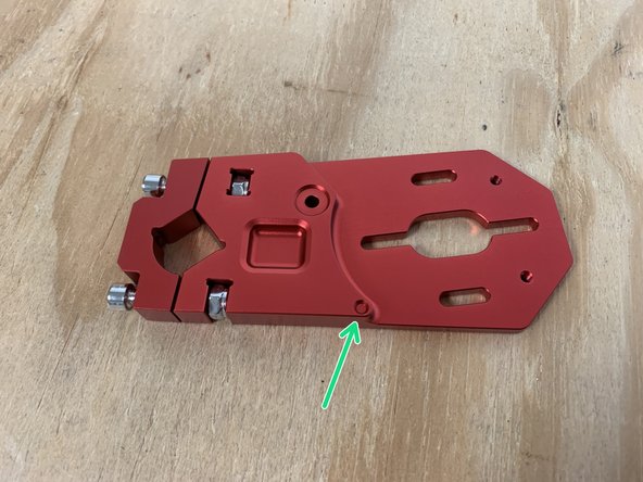
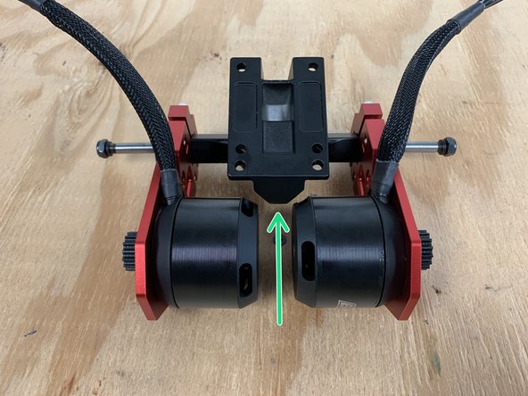
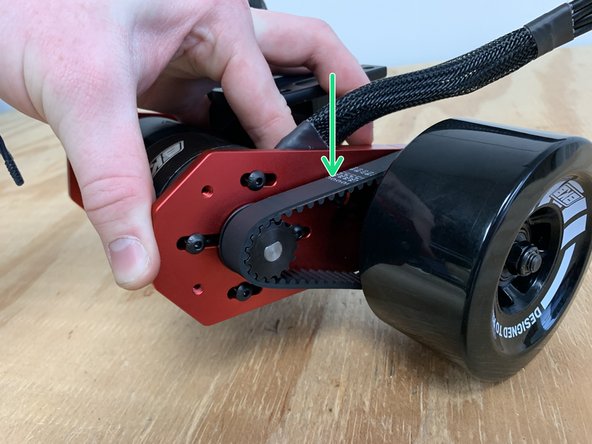
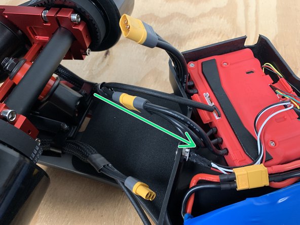
Test the tension by pressing down in the area located by the green arrow. The belt should move up and down 2-3mm with your press.
-
If it is too stiff and does not move, there is too much tension in the belt. Loosen the bolt and try again
-
If the belt depresses more than 4mm, there is not enough tension. Loosen the bolt and apply more tension.
-
When the proper tension has been achieved, tighten all four bolts to lock the motor in position.
-
If there is a problem in the future with the motor not gripping the belt tightly, consider re-tightening these motor-mount bolts.
-
-
-
Repeat steps 18-20 to complete assembly of the other side of the drivetrain. Ensure proper belt tension
-
RailCore board? Time to switch back to your RailCore Tutorial! (Skip to step # 19!)
-
-
-
Gather the drivetrain, front truck, top rails, risers, truck hardware, wrench, 3mm Allen wrench, and deck
-
97mm Wheels - The risers are not always required. We strongly recommend starting with them installed because the enclosure for the battery and ESC hangs low on the board and may scrape certain objects as you ride. The risers will provide additional ground clearance to prevent this from happening.
-
105mm Cloud Wheels - We only recommend these risers if the board will be carrying more than 200lbs, the flex to the deck and additional ground clearance will offer the best experience.
-
6in AT Wheels - These risers are not necessary unless more ground clearance is required for rough terrain.
-
-
-
Open the small plastic package with hardware labeled "TRUCKS"
-
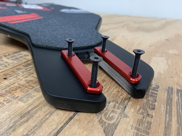
There are two different top metal rails, a left and a right, look at the angled portions closely to map these to the board angles.
-
Take a left and right rail, place the truck bolts through them and then press the bolts through the front of the deck
-
When the deck is positioned grip-tape down, the pad is the rear of the board. The pad is designed to support and seal the battery and electronics enclosure.
-
Add a riser to the underside of the deck over the bolts
-
Slide the front truck over the bolts and then secure it by installing a locknut on each bolt.
-
Hold the bolt in place with the wrench, and rotate the allen wrench for the fastest method of attaching these bolts.
-
-
-
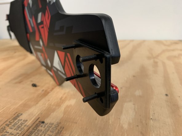
Repeat the previous step for the rear truck metal attachments. Place bolts through the top rails and then through the deck as shown.
-
Add a riser to the underside of the deck over the bolts
-
Add the drivetrain with the motors facing the rear to the bolts. (do not add the locknuts yet, we will attach wire hangers in a moment)
-
-
-
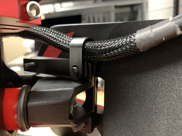
Add a wire clip to each motor and orient them as shown. Attach the wire clips to the two inner bolts.
-
Secure all four bolts with a locknut each
-
-
-
If your Xenith was already installed in the enclosure do NOT remove it. You can skip the following steps where it is installed
-
NOTE: If you purchased the Bluetooth module it will be pre-installed under the silicone case of the Xenith. So it will not be visible, but it is there.
-
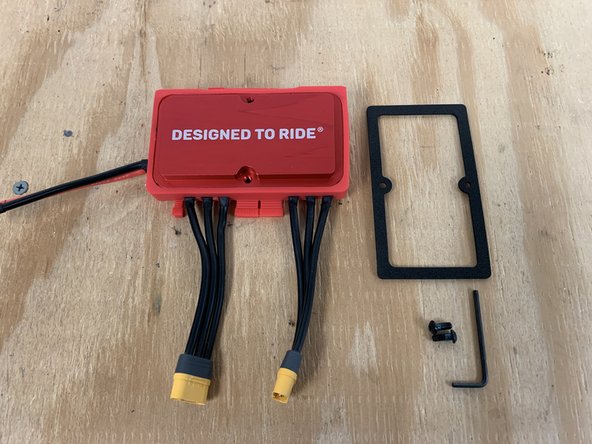
Gather the Xenith, Xenith gasket, M4x10 button head bolts, and 2.5mm Allen wrench
-
Remove the paper backing off of the gasket, then slide it over the red heatsink pressing the glue firmly in place. Careful to avoid gaps, bubbles or a mis-aligned gasket.
-
The glue for the gasket may make removing the paper difficult, if the gasket does not have glue on it, and the paper is difficult to remove then try a different spot on the paper backing using a razor blade, tweezer or needle-nose pliers.
-
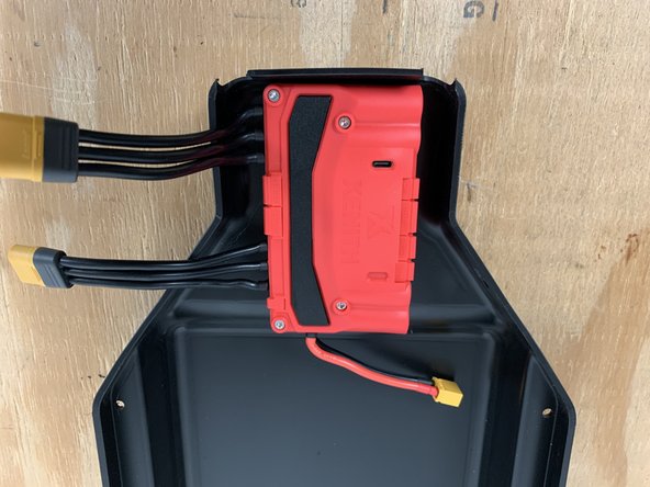
Place the Xenith in the enclosure as shown. If positioned properly, the battery wire will be going deeper into the enclosure.
-
-
-
Add a drop of Loctite to each bolt and then secure the heatsink to the enclosure
-
-
-
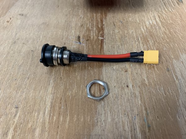
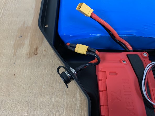
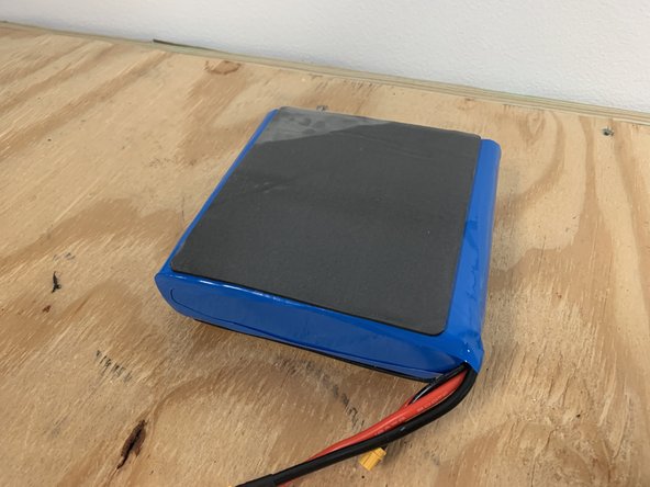
Find the battery assembly, attached to the battery is the charge port, disconnect it using the yellow connector for this step.
-
Remove the locknut from the charge port
-
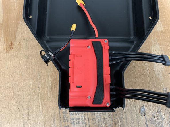
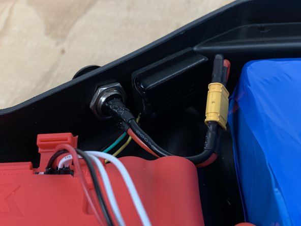
Slide the charge port through the hole in the left side of the enclosure
-
Reinstall the locknut to secure the charge port
-
-
-
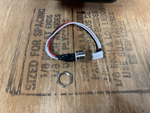
Remove the locknut from the switch
-
Place the switch in the hole on the right side of the enclsoure
-
Reinstall the locknut to secure the switch
-
-
-
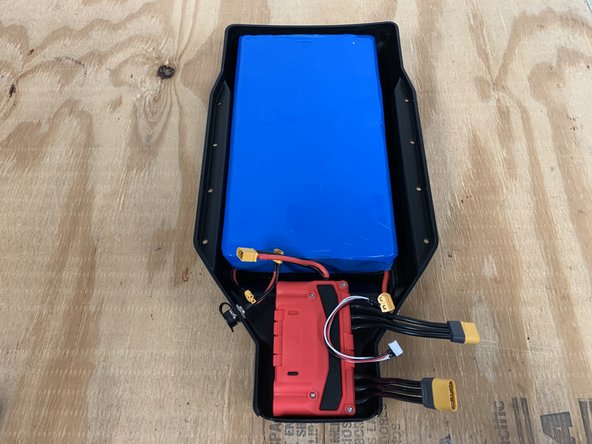
Place the battery inside the enclosure
-
If you have the standard 10s3p Battery please see the next step for placement
-
Plugin the battery to the Xenith
-
-
-
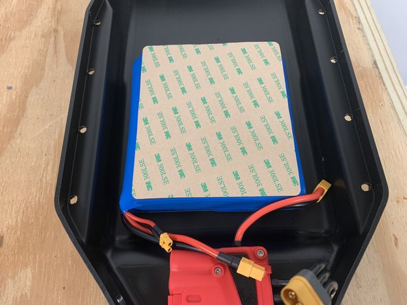
This step is only for users with the smaller 10s3p battery. Type R users can skip.
-
The10s3p battery has a wide side and a shorter side. Peel the paper backing off of the gasket on the wide side. Leave the paper on the short side
-
Firmly press the battery into the enclosure as shown so charge port and battery wires are near the charge port side
-
-
-
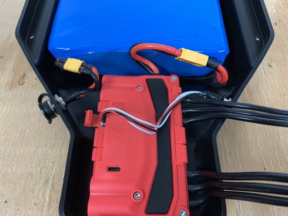
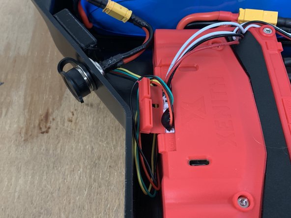
Plugin the switch to the SWITCH port on the Xenith
-
Tuck all of the wires in neatly
-
-
-
Peel the paper backing off of the receiver and then place it in the enclosure as shown next to the charge port
-
Plug the receiver into the UART port on the Xenith
-
-
-
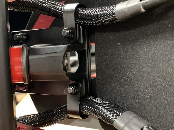
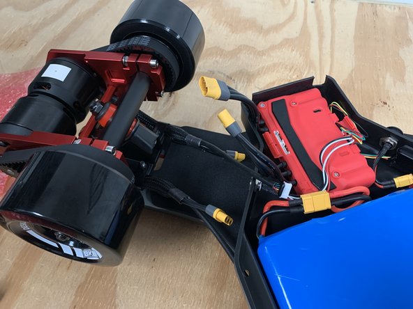
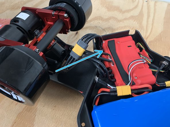
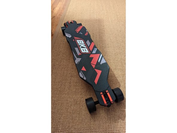
Position the enclosure, deck, and motors as shown
-
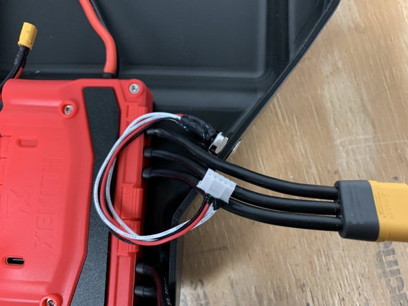
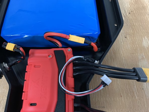
Plug the upper motor cables into the Xenith cables as shown. Do NOT swap the cables. Be extra sure they are plugged in EXACTLY as shown
-
You plug the yellow motor connectors together as well as place the white motor connector into the MSENSOR port on the Xenith (there are two ports, reference the photo to see where to plug them in)
-
Then plug the lower motor cables into the upper Xenith cables. Double check the wiring is exactly as shown
-
-
-
Now it is time to attach the enclosure to the deck. This is the trickiest part to the entire build. Be sure to take your time, and restart if need be. The first time you do it, it will take forever to complete. Once you get the hang of the process it will be much easier to do in the future. Take your time.
-
-
-
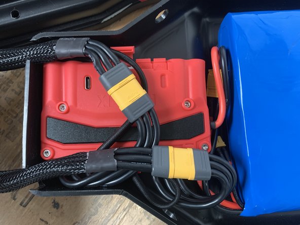
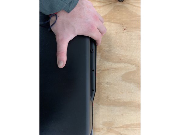
To attach the enclosure you will need to fold all of the wires flat and ensure the large yellow connectors are laying flat as well.
-
Position all of the wires as shown. Then use your hand to keep all wires in place and flip the enclosure over. Ensure you are flipping it the correct direction so the motor wires untangle themselves. They should now be straight directly from the motor and into the enclosure
-
If the enclosure does not sit flat, use your hand to move the wires around inside the enclosure until everything fits
-
-
-
It is important to attach the bolts in the correct order so that all bolts, and correct alignment for the enclosure is achieved. Follow the steps below carefully.
-
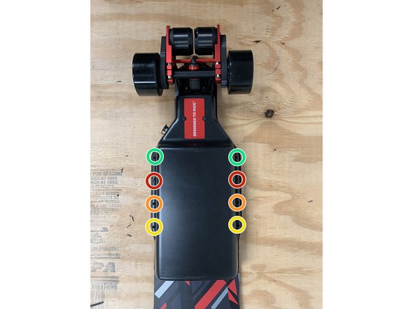
Align the enclosure over the deck's bolt holes, note that these holes are threaded. Prepare the enclosure bolts. Add a metal washer and rubber washer to each bolt. The order of parts when assembled should be bolt, metal washer, rubber washer, enclosure. Add a drop of loctite to each bolt!
-
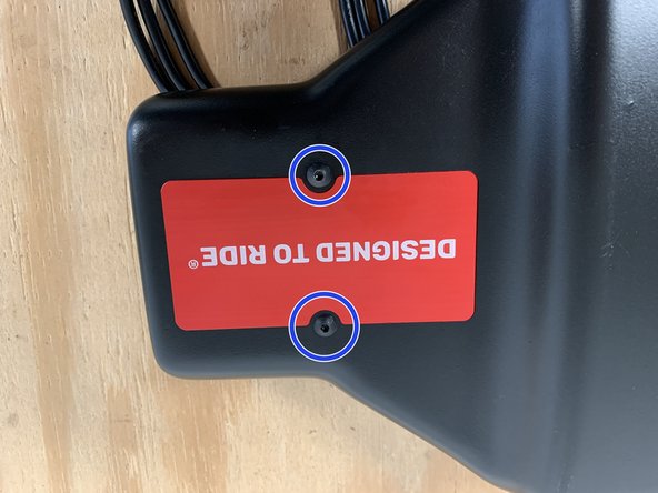
Add the bolt to the left side, second from the top (red circle). Do not tighten it fully, get the threads started (loctite)
-
Then add the bolt to the other side (right red circle). Do not tighten fully. You may need to provide some force to move the enclosure towards the bolt holes as shown in the second photo (loctite)
-
Then add the two bolts in the orange circles (loctite)
-
Add the bolts to the yellow circles (loctite)
-
Finally add the bolts to the green circles
-
After all bolts are started, tighten them in the same order to the point where the rubber washer is compressed, but not misshapen. If you cannot get a bolt to start threading, remove all of the bolts. Then start with the bolt that wouldn't start threading and continue adding all of the bolts.
-
-
-
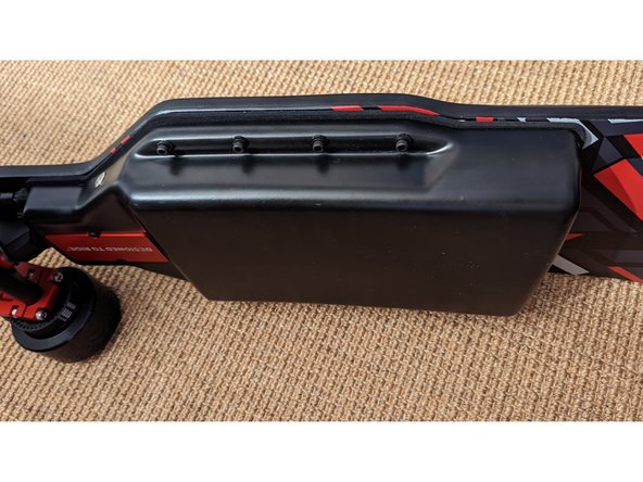
The loctite needs 24 hours to fully cure. If you are anxious to try things out wait 2 hours before riding so that the enclosure bolts do not fall out.
-
After your first ride, whenever that may be, ensure the enclosure bolts did not come loose. Tighten them and add loctite as necessary.
-
While you wait for the loctite to cure, charge the battery and program the remote.
-
The battery is partially charged when shipped. Take care to follow typical lithium ion battery care. Do not trickle charge, charge only to 80% each time for longest life, reduce charge to 40% and keep in a cool place if in storage to retain battery life.
-
For the technical minded, the maintenance of Lithium batteries is explained in this PDF ( Consider mirroring this content in a better location ...
-
-
-
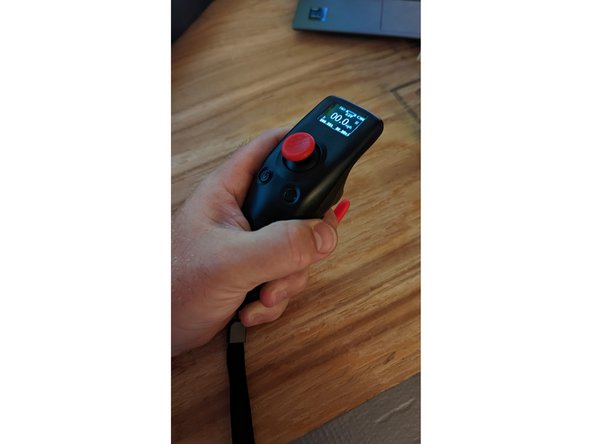
WARNING: Make sure the BKB board is turned off, with wheels facing up! Then turn the remote on by long pressing the power button (left)
-
Enter the settings menu by long pressing the settings button (right)
-
Click enter (right button) to enter the board parameters menu
-
Press enter to enter the battery cells setting
-
Move the throttle up and down to change the value. If you have the small battery (10s3p) ensure the value is 10S. If you have the larger battery (TypeR) ensure the value is set to 12S. When the value is set press the exit button (left).
-
Use the throttle to navigate the other settings within the board parameter menu. Change the values to match your current setup
-
Pole Pairs = 7. Wheel Type = Pulleyed. Wheel Diamater = 97mm, 105mm, or 150mm depending on your wheel choice. Motor pulley = 15C for standard and 20C for the speed upgrade. Wheel pulley = 40C for 97 or 105mm wheels, 60C for 6in wheels. Unit = your choice. Xenith FW = DISABLE. Then click exit to return to the menu.
-
Navigate to the Remote Config menu and press enter. Go to the gear calibration and press enter. Apply full throttle, then full brake, then full throttle, and then full brake. Press and hold the save button. Then click exit to return to the menu
-
-
-
We will now pair the remote to the receiver. Ensure that the skateboard is turned off. Navigate to the Receiver Config menu, press enter.
-
Click enter on BINDING. The words will then begin to blink. Then turn the board on and the remote will pair. Click exit twice to return to the main screen.
-
You can learn more about how to use the remote here: Using the Voyager Remote
-
It is highly recommended to ride the board for the first time in the low acceleration mode.
-
-
-
ALWAYS WEAR A HELMET! THEY SAVE LIVES. DONT WEAR IT FOR YOU, WEAR IT FOR YOUR FAMILY.
-
Electric skateboarding is a very fun and rewarding sport. But, everyone has fallen off their board at some point. It's not a matter of if it will happen, but when it will happen. Please wear at least a helmet and always ride within your comfort zone
-
Treat the board with respect! It is a vehicle after all. Do NOT drop the board from a vertical position to set it down as it put a lot of stress on the enclosure. Give the board a good once over before every ride to make sure bolts are tight and things look normal.
-
NEVER CHANGE THE FIRMWARE ON THE XENITH! IF YOU ARE HAVING AN ISSUE REACH OUT TO SUPPORT BEFORE CHANGING ANY SETTINGS ON THE XENITH!
-
Please consider leaving a review on our website and helping us spread the word on Facebook/Reddit/Instagram/etc. We do NOT do any paid marketing, we believe the product and our customers speak for themselves. Every little bit helps!
-


Cancel: I did not complete this guide.
2 other people completed this guide.
