
Tools
Parts
-
-
Use the VESC Tool FW5.3 to connect to your ESC
-
Under the App settings -> General tab change the control mode to UART
-
Under the App settings -> UART tab set the baud rate is set to 115200
-
Under the App settings -> VESC Remote tab set the Control Type to Current and Use Smart Reverse to False
-
Apply the settings to the ESC by pressing the down arrow A. If you have any trouble writing the settings to the ESC, unplug the receiver.
-
-
-
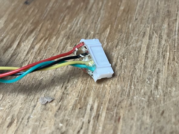
Choose the correct cable depending if you have a V4 or V6 ESC
-
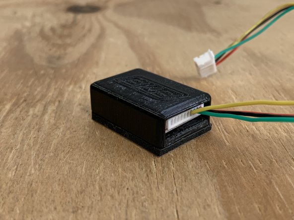
Carefully plug the cable into the receiver. There are two small blocks on the cable, they should face down and the pins should face up
-
-
-
Place the receiver inside the 3d printed housing. UPDATE: We now provide shrink wrap instead of the 3D printed housing.
-
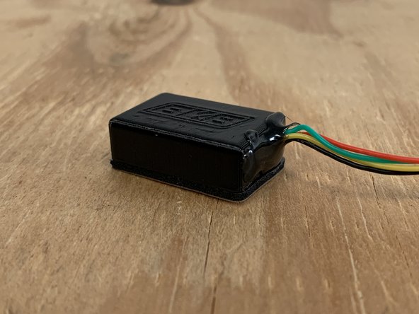
Fill the gap with hot glue, and secure the connection from the cable to the plug with the hot glue.
-
Add hot glue to the connector that plugs into the VESC
-
UPDATED: If using shrink wrap, use a heat gun or hairdryer to shrink the wrap around the PCB. Be careful, too much heat will make the hot glue liquid again.
-
Adding hot glue to BOTH ends of the connector is very important
-
-
-
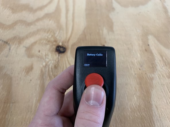
Turn the remote on by pressing and holding the power button (left)
-
Go into the settings menu by pressing and holding the settings button
-
-
-
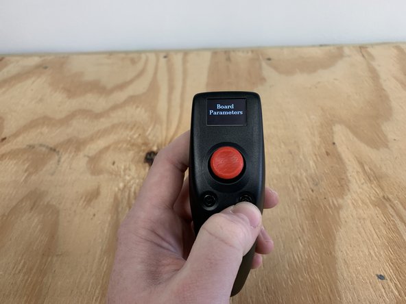
Here is where you will customize the settings of the remote
-
Click ENTER (right button) to open the board parameter settings
-
Move the joystick up and down to select a setting you want to modify. Then click ENTER
-
Move the joystick up and down to adjust the value. Then press EXIT when the value is set properly
-
Adjust all of the settings in the Board Parameters Menu
-
-
-
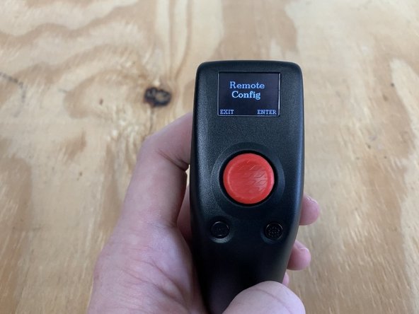
Then click EXIT to return to the main menu. Navigate to the REMOTE CONFIG menu. Press ENTER
-
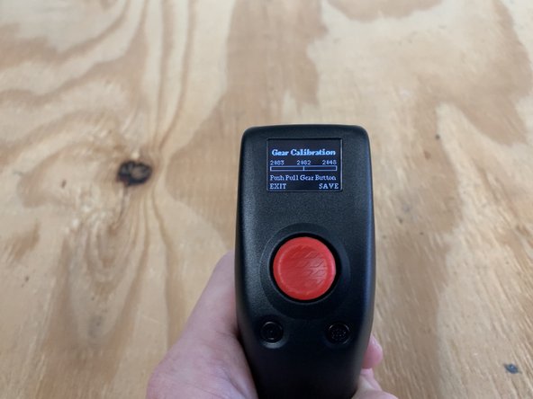
Navigate to the GEAR CALIBRATION setting. Press enter.
-
Apply full throttle (forward) and full brake (backward) to the joystick. Repeat to do this twice
-
Press and hold SAVE for two seconds
-
-
-
Ensure that the board / ESC is in the off position.
-
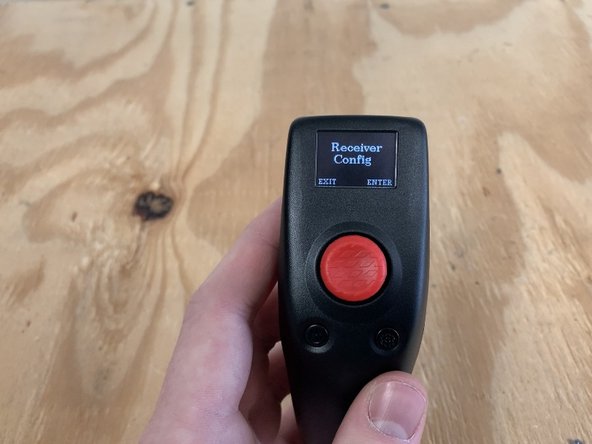
Navigate back to the RECEIVER CONFIG area. Press ENTER
-
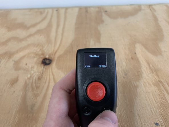
Navigate to the BINDING setting. Press ENTER.
-
Plugin the receiver to the ESC UART port (or turn on the board if you are re-pairing the remote).
-
-
-
Remove the backing off of the gasket to stick the receiver box to the enclosure
-
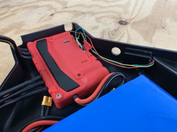
VERY IMPORTANT!!! Do NOT place the receiver near any motor or battery wires. They can cause interference. Make sure the receiver is as far from any wires as possible.
-
As seen in the photo, the receiver is on the opposite side of the power and motor wires.
-


Cancel: I did not complete this guide.
One other person completed this guide.

One Comment
Simple shielding for any cables can be done with a bit of aluminum foil and a bit of electrical tape to hold it all in place. It may not be the prettiest, but it should properly shield the cables from EMI. To properly drain it should also be connected with a lead to “ground” - which I will have to let BKB describe the best location to tap.
Bryant Eadon - Resolved on Release Reply